13 Maintenance and Inspection
13 - 12
High-function General-purpose Inverter RX2 Series User’s Manual
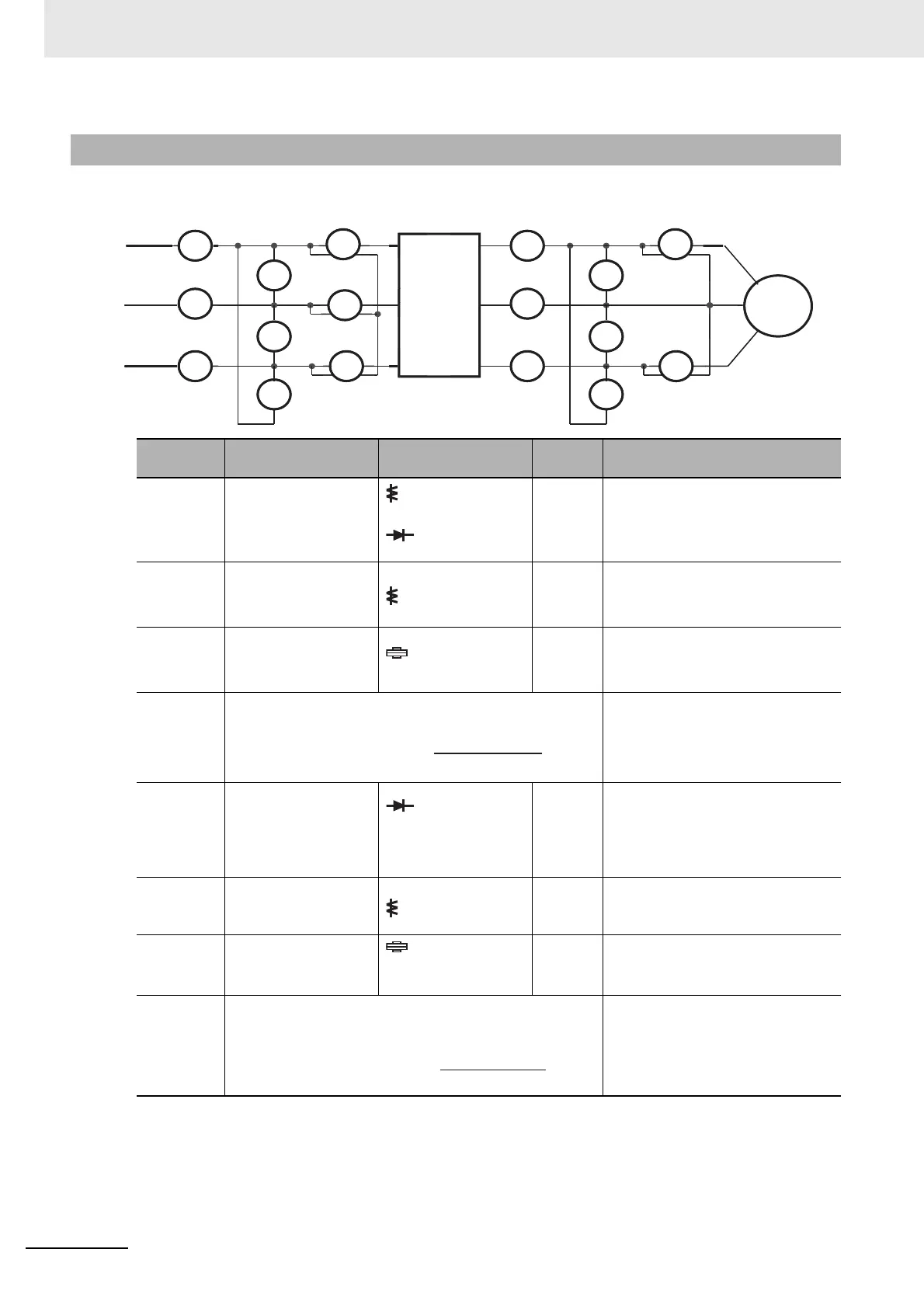
The following shows general measurement instruments used for measurement of input/output voltage,
current, and power.
13-5-4 Measurement Method of I/O Voltage, Current, and Power
Measure-
ment item
Target section
Measurement
instrument
Remarks
Criteria
Power
supply
voltage
E
IN
Between R-S, S-T, and
T-R
(E
R
), (E
S
), (E
T
)
Moving iron voltmeter
or
Rectifier type
voltmeter
All
effective
values
200 V class: 200-240 V 50/60 Hz
400 V class: 380-500 V 50/60 Hz
Power
supply
current
I
IN
Current of R, S, and T
(I
R
), (I
S
), (IT)
Moving iron ammeter
All
effective
values
If input current is imbalanced
I
IN
=(I
R
+I
S
+I
T
)/3
Power
from power
supply
W
IN
Between R-S, S-T, and
T-R
(W
I1
)+(W
I2
)+(W
I3
)
Electrodynamome-
ter type wattmeter
All
effective
values
Three wattmeter method
Power rate
of power
supply
P
fIN
Output
voltage
E
OUT
Between U-V, V-W,
and W-U
(E
U
), (E
V
), (E
W
)
See the figure
below
or
Rectifier type voltmeter
Effective
value of
funda-
mental
wave
Output
current
I
OUT
Current of U, V, and W
(I
U
), (I
V
), (I
W
)
Moving iron ammeter
All
effective
values
Output
power
W
OUT
Between U-V and V-W
(W
O1
)+(W
O2
)
Electrodynamome-
ter type
wattmeter
All
effective
values
Two wattmeter method
(or three wattmeter method)
Output
power
factor
P
fOUT
Power
supply
Inverter
Motor
This value is calculated using measurement values of
power supply voltage E
IN
, power supply current I
IN
, and
power supply power W
IN
.
P
fOUT
W
OUT
×100
=
√
3
∙E
∙I
OUT OUT
This value is calculated using measurement values of
output voltage E
OUT
, output current I
OUT
, and output
power W
OUT
.

 Loading...


