2 - 9
2 Design
High-function General-purpose Inverter 3G3RX-V1 User’s Manual (I578-E1)
2-2 Removal of Each Part
2
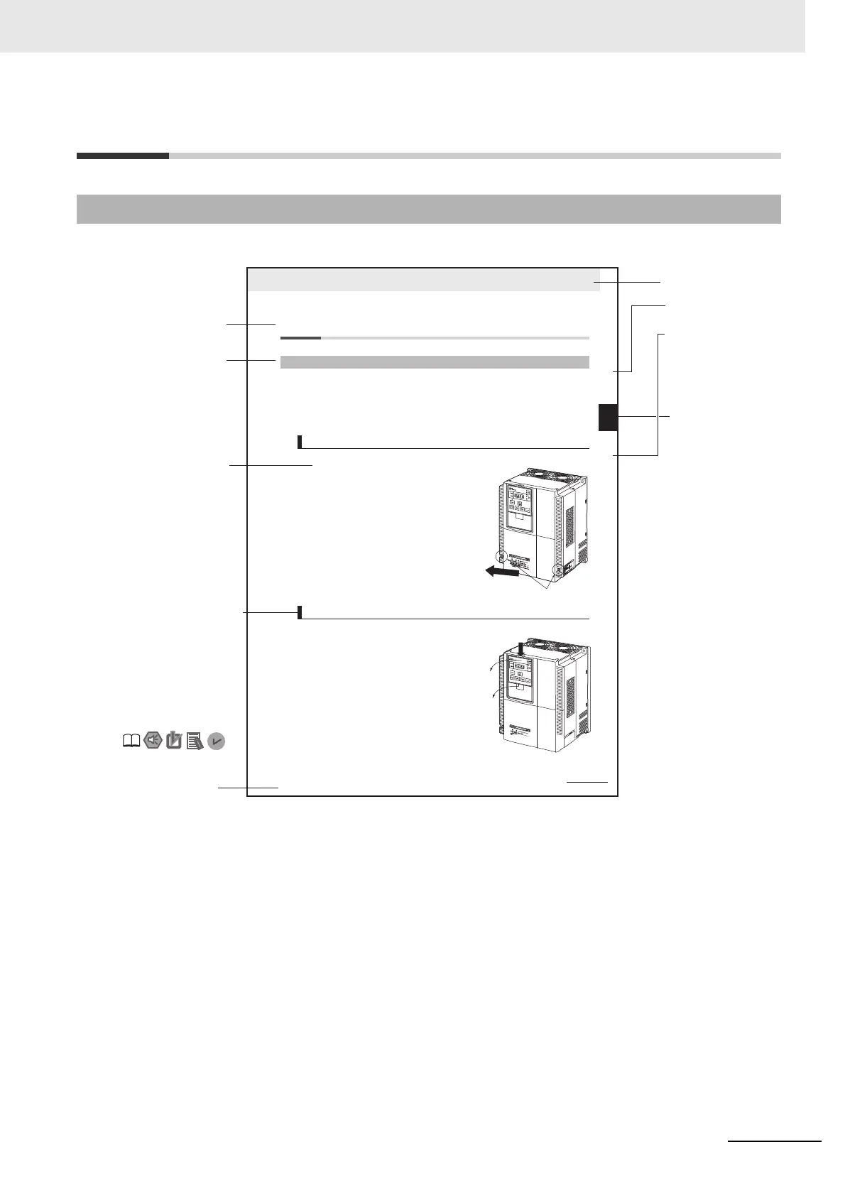
2-2-1 Removing Covers
2-2 Removal of Each Part
Before wiring each terminal block, you need to remove the terminal block cover and the backing plate.
In addition, to install a PG Board or communications unit, you must remove the Digital Operator, spacer
cover, terminal block cover, and front cover beforehand.
This section describes how to remove these covers.
To reinstall it, reverse the removal procedure.
1
Loosen the terminal block cover fixation screws.
There are two terminal block cover fixation screws,
one for each side of the cover.
Larger capacity Inverter models have three terminal
block cover fixation screws.
2
Remove the terminal block cover in the direction of
(a) while holding it from the bottom.
1
Remove the Digital Operator in the direction of (a) by
pushing the lip on the top.
2
In the same way, remove the spacer cover in the
direction of (b).
2-2-1 Removing Covers
Removing Terminal Block Cover
Removing Digital Operator and Spacer Cover
(a)
Terminal block cover fixation screws