8 - 33
8 Applied Settings
High-function General-purpose Inverter RX2 Series User’s Manual
8-1 PID Control
8
8-1-6 PID Signal Output
This is a function to clear an integral figure of the corresponding PID operation.
In the case of turning ON the [PIDC2]/[PIDC3]/[PIDC4] terminal, do so when the corresponding PID is
not in operation.
Precautions for Correct Use
Turning ON the [PIDC2]/[PIDC3]/[PIDC4] terminal during PID operation clears the integral
value added to the PID output command and changes the PID output command value abruptly,
resulting in an over-current error.
Turning ON the corresponding terminal disables PID operation temporarily and performs output accord-
ing to frequency command.
The figure input as PID command will be adopted for frequency command.
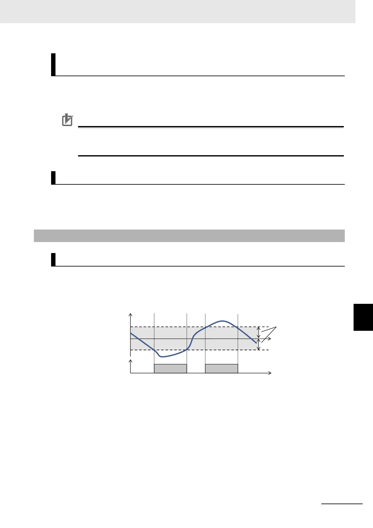
This outputs a deviation excessive signal in the case of each PID deviation exceeding the set level of
the corresponding PID.
Assign output terminal 11 to 15 selection (CC-01 to CC-05) or relay output terminal (16, AL) selection
(CC-06/CC-07) to 045 (OD).
PID2/PID3/PID4 I Control Integral Reset Function
[PIDC2]/[PIDC3]/[PIDC4]
PID2/PID3/PID4 Disable Function [PID2]/[PID3]/[PID4]
8-1-6 PID Signal Output
PID Deviation Excessive Signal (OD)
0%
[AH-72] /
[AJ-17]/
[AJ-37]/
[AJ-57]
OD/OD2/OD3/OD4
ON ON
PID deviation (%)
PID1 deviation/
PID2 deviation/
PID3 deviation/
PID4 deviation
PID deviation
excessive level
Time (s)