8 - 167
8 Applied Settings
High-function General-purpose Inverter RX2 Series User’s Manual
8-10 Input Terminal Function
8
8-10-6 Pulse Count Function
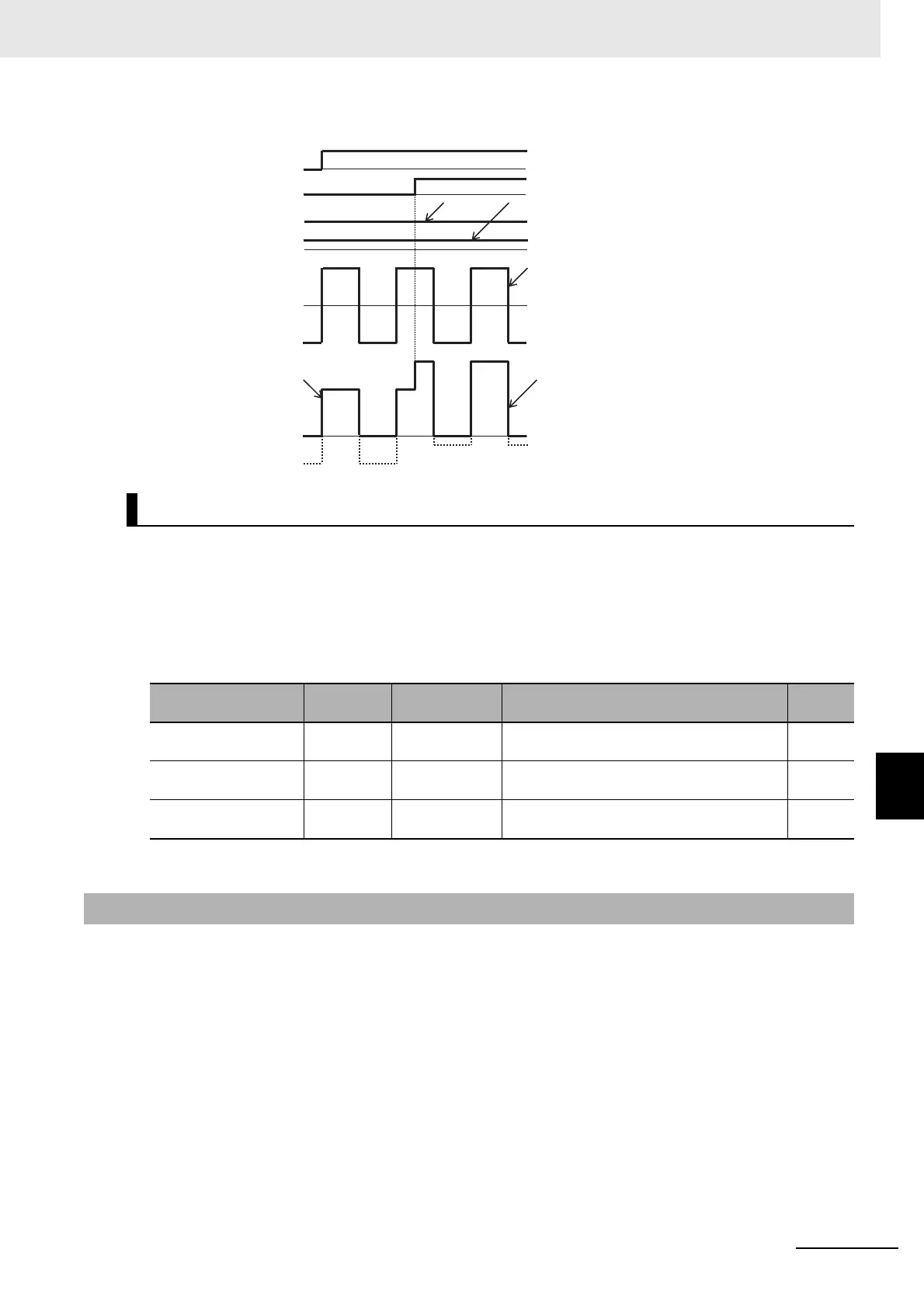
(Ex.4-2) [Cb-22]=02 (without reversibility)
To give a frequency instruction with an external analog signal, you can set a sampling time for voltage
input or current input.
This feature is effective for removing noise from the frequency setting circuit.
Increase the set value if noise negatively affects a stable operation. Note that the greater the set value,
the lower the responsiveness. When this feature is used for a PID instruction, and a filter is set, the filter
would affect the feedback, and therefore a fine operation would not be achieved.
For the pulse counting function, the terminal input monitoring mode and the phase coefficient monitor-
ing mode are available.
When the “Selection of targets for pulse string input detection [CA-90]” ranges from 00 to 02, the termi-
nal input monitoring mode becomes valid. When [CA-90] is set to “03 (pulse count),” the phase coeffi-
cient monitoring mode becomes valid.
You can monitor the acquired pulses with the pulse counter monitor served as an accumulation counter.
By turning on [PCC] (Clearing of pulse counter), you can clear the accumulated counter value.
Analog Input Filter Settings
Item Parameter Data Description
Default
data
Filter time constant of
Terminal [Ai1]
[Cb-01] 1. to 500.(ms) Sets a time constant for the input filter. 16
Filter time constant of
Terminal [Ai2]
[Cb-11] 1. to 500.(ms) Sets a time constant for the input filter. 16
Filter time constant of
Terminal [Ai3]
[Cb-21] 1. to 500.(ms) Sets a time constant for the input filter. 16
8-10-6 Pulse Count Function
F(Ai1)
F(Ai2)
F(Ai2)+ F(Ai3)
0
AT
F(Ai2)
0
0
F(Ai1)+ F(Ai3)
FW
Main speed/auxiliary
speed instruction
[Ai1]/[Ai2] terminal
Actual frequency
instruction
Addition
instruction
[Ai3] terminal
Normal
rotation