8 Applied Settings
8 - 168
High-function General-purpose Inverter RX2 Series User’s Manual
Precautions for Correct Use
• The maximum input pulse in the phase coefficient monitoring mode becomes a maximum of
32 kpps. (When the duty ratio is approximately 50%)
• An accumulation counter value cannot be stored. After the power supply is turned on, the
value becomes zero.
• The maximum input pulse in the terminal input monitoring mode depends on the settings of
the input terminal response functions [CA-41] to [CA-51].
Parameter
Monitors whether the input terminal functions [PLA] and [PLB] are turned on.
Item Parameter Data Description
Default
data
Input terminal function
[CA-01] to
[CA-11]
103 [PLA]: Accepts a pulse input.
-104 [PLB]: Accepts a pulse input.
097 [PCC]: Clears the integrated value.
Output terminal func-
tion
[CC-01] to
[CC-07]
091
[PCMP]: Outputs pulse compare-match sig-
nals.
-
Pulse train detection
object selection
[CA-90]
00 Disabled
00
01 Frequency command
02 Speed feedback
03 Pulse count
Mode selection of
pulse train input
[CA-91]
00 90° phase difference
0001
forward/reverse rotation command and rota-
tion direction
02 forward/reverse rotation pulse string
Comparing match out-
put ON-level for Pulse
count
[CA-97] 0 to 65535
When the number of pulses reaches this set
value, Turn on [PCMP].
0
Comparing match out-
put OFF-level for
Pulse count
[CA-98] 0 to 65535
When the number of pulses reaches this set
value, Turn off [PCMP].
0
Comparing match out-
put Maximum value for
Pulse count
[CA-99] 0 to 65535
A one-shot pulse can be achieved when the
value is 0.
When the number of pulses reaches the set
value, the internal counter is cleared.
0
Pulse counter monitor [dA-28]
0 to
2147483647
Displays the counter integrated value. -
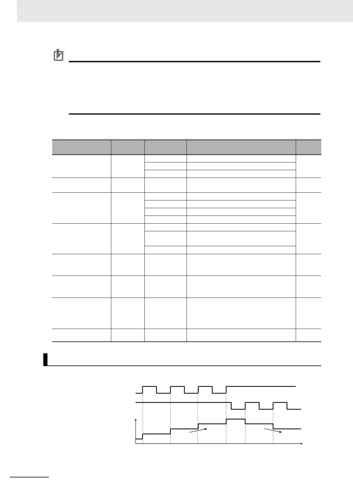
Terminal Input Monitoring Mode
Normal rotation
pulse string input
Number of detected pulses
Terminal
[PLA]
Reverse rotation
pulse string input
Terminal
[PLB]