Appendices B STO Function
B - 12
High-function General-purpose Inverter RX2 Series User’s Manual
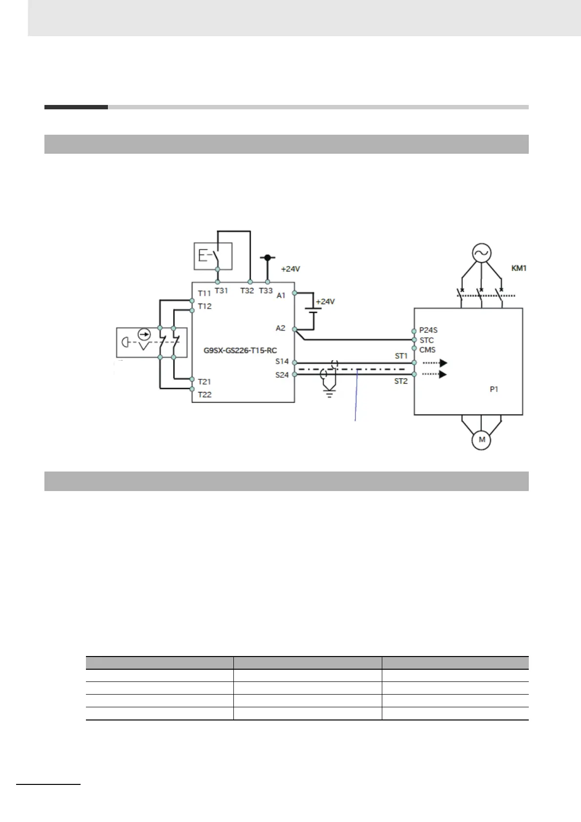
B-3 Example of Use
Procedure for connecting STO input to a safety controller is shown as an example.
The condition for use is the followings:
• Use external power supply as one for STO input.
• Never use EDM output.
Power supply connected to control terminals in 3G3RX2-series is needed to comply with SELV and
PELV.
Each ST1/ST2 signal must be separated physically and protected appropriately.
Device for communication of STO signals shall comply with safety standards like ISO13849-1 and
IEC61508, etc.
A safety system includes 3G3RX2-series must fulfill CAT.3, PL e /SIL3. Therefore, the 3G3RX2-series
must be combined with external safety devices that meet PL e/SIL3.
Test pulse input to ST1/ST2 shall be 300 us or less.
Combination of 3G3RX2-series with external safety devices is shown as below.
B-3-1 Example of Wiring
B-3-2 External Device
Manufacturer Product Model Applicable standard/criteria
OMRON G9SA-301 ISO13849-1 cat4, SIL3
OMRON G9SX-GS226-T15-RC IEC61508 SIL1 to 3
OMRON NE1A-SCPU01-V1 IEC61508 SIL3
OMRON G9SP-N IEC61508 SIL3
Separated physically or
provided cable protection
(double shielded)
STO Input
Reset
Switch
Safety switch
(Ex: Emergency Button)
STO Output
Safety unit
* Applicable standard
(IEC61508, ISO13849)