8 - 177
8 Applied Settings
High-function General-purpose Inverter RX2 Series User’s Manual
8-11 Output Terminal Function
8
8-11-3 Output Terminal ON Delay/OFF Delay
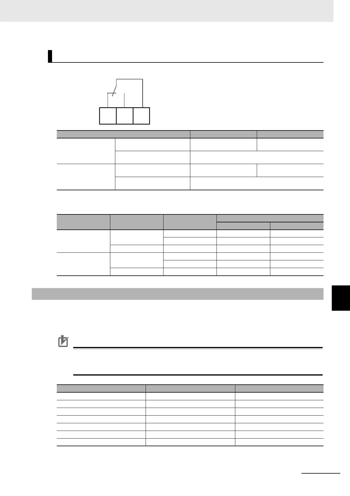
The specification of Relay 1c output terminals AL1 to AL0/AL2 to AL0 are as shown below.
• The operations of AL1 to AL0/AL2 to AL0 are as shown below.
You can set an on-delay/off-delay time per output terminal.
You can make a setting per output terminal. For the correspondence between output terminals and
parameters, please refer to the table shown on the below.
Precautions for Correct Use
All output signals immediately turn ON/OFF upon a condition is satisfied. Chattering could
occur depending on a selected signal. This function is available for retaining/delaying such a
signal.
Relay 1c Output Terminals
Resistance load Induced load
AL1-AL0
Maximum contact capacity
AC250V, 2A
DC30V, 3A
AC250V, 0.2A
DC30V, 0.6A
Minimum contact capacity
AC100V, 10mA
DC5V, 100mA
AL2-AL0
Maximum contact capacity
AC250V, 1A
DC30V, 1A
AC250V, 0.2A
DC30V, 0.2A
Minimum contact capacity
AC100V, 10mA
DC5V, 100mA
[CC-17]
Control power
supply
Output of inverter
function
Output terminal state
AL1-AL0 AL2-AL0
00
On
ON Close Open
OFF Open Close
Off - Open Close
01
(Initial value)
On
ON Open Close
OFF Close Open
Off - Open Close
8-11-3 Output Terminal ON Delay/OFF Delay
Output terminals On-delay time Off-delay time
11 [CC-20] [CC-21]
12 [CC-22] [CC-23]
13 [CC-24] [CC-25]
14 [CC-26] [CC-27]
15 [CC-28] [CC-29]
16A-16C [CC-30] [CC-31]
AL1-AL0/AL2-AL0 [CC-32] [CC-33]