9 - 9
9 Communications Functions
High-function General-purpose Inverter RX2 Series User’s Manual
9-3 Explanation of Each Function Code
9
9-3 Explanation of Each Function Code
Reads the coil status (ON/OFF).
Precautions for Correct UsePrecautions for Correct Use
The byte order was changed when data over 1 bite is processed with reading function of sev-
eral coils via Modbus communication.
Receive data in the data layout as shown below, according to the number of data bytes to be
read.
• Data received as 1-byte data (1 to 8 coils)
• Data received as 2-byte data (9 to 16 coils)
• Data received as 3-byte data (17 to 24 coils)
• Data received as 4-byte data (25 to 32 coils)
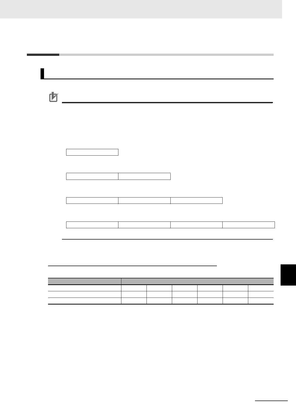
Example
When inverter’s input terminal function 1 to 6 with slave address 8 is read out
, the input terminal status
is shown as below table.
Coil numbers 000B hex and 000C hex are OFF.
Read Coil Status [01 hex]
Coil 8 to Coil 1
Coil 8 to Coil 1 Coil 16 to Coil 9
Coil 8 to Coil 1 Coil 16 to Coil 9 Coil 24 to Coil 17
Coil 8 to Coil 1 Coil 16 to Coil 9 Coil 24 to Coil 17 Coil 32 to Coil 25
Item Data
Input terminal No. 1 2 3 4 5 6
Coil number 0005 hex 0006 hex 0007 hex 0008 hex 0009 hex 000A hex
Terminal status ON ON ON OFF ON OFF