7 Advanced Settings
7 - 80
High-function General-purpose Inverter RX2 Series User’s Manual
Before outputting the frequency to the motor, perform the servo-lock to stop the motor rotating. And
then, start operation.
To apply DC braking for starting (servo-lock control), the following settings are required:
• [AA121] Control mode (see below)
• Set [AF101] DC braking selection to 01
• Set [AF102] Braking mode selection to 01 or 02.
• Set [AF109] DC braking time for starting to other than 0.0
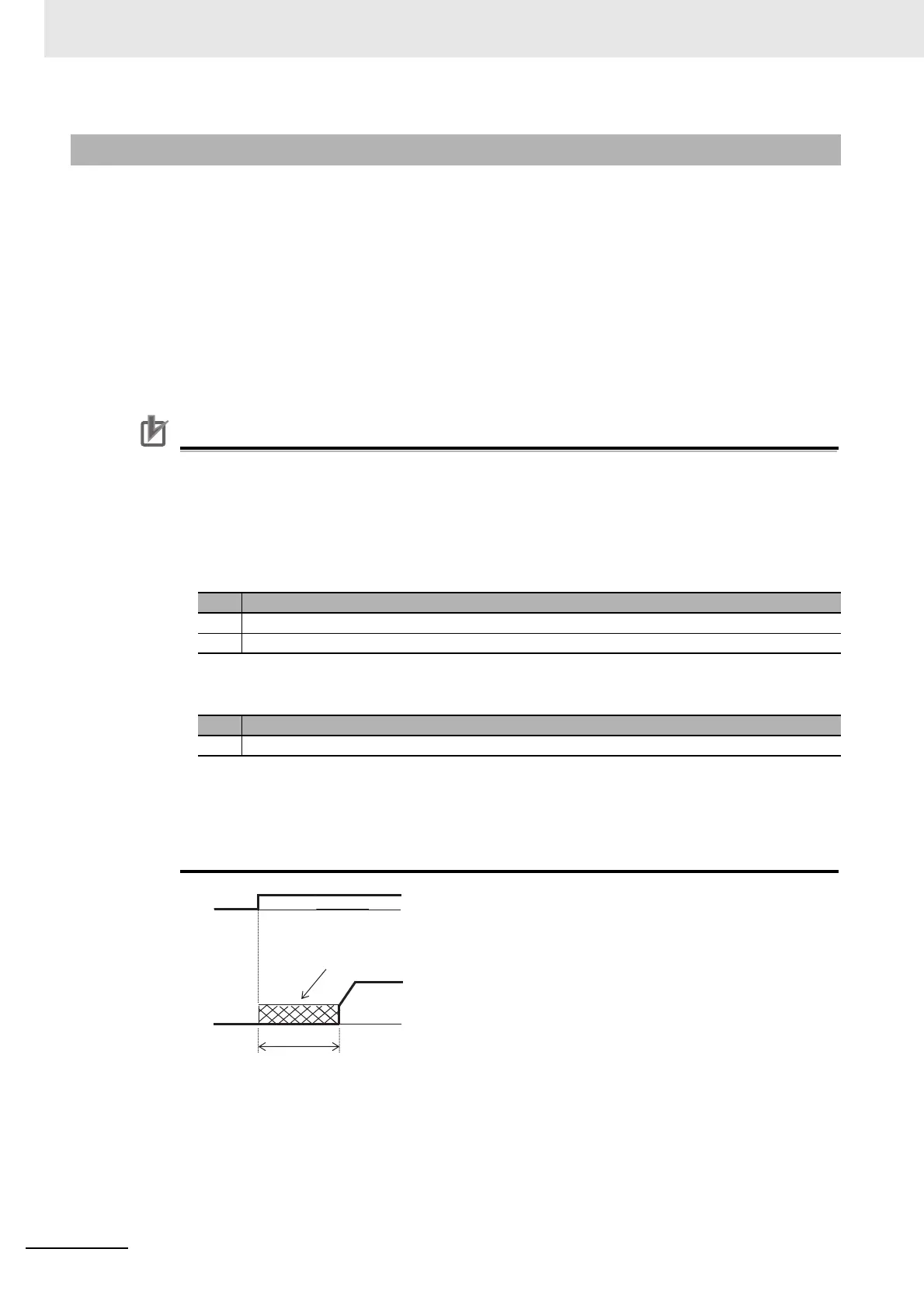
If the DC braking for starting (servo-lock control) is enabled, DC braking (servo-lock control) will be per-
formed after the operation command is given, for the period of time set as DC braking time for starting
[AF109].
Precautions for Correct Use
• Depending on the set braking force, the carrier frequency may automatically go down to pro-
tect the inverter.
• To use the servo-lock control, it is necessary to set [AA121] Control mode. If the applicable
control mode is not selected, the inverter will operate as if [AF102] has been set to 00: DC
braking.
(1)When [AF102] Braking mode selection is set to 01: Speed servo-lock
(2)When [AF102] Braking mode selection is set to 02: Position servo-lock
• For [AA121] Control mode and [AA123] Vector control mode selection, it is necessary to set .
See 7-1 Overview of Motor Control Methods on page 7-3.
• The output of the servo-lock control is automatically calculated according to the selected con-
trol mode.
7-5-9 Startup DC Injection Braking (Servo Lock Control)
No. [AA121] Control mode
1 09: Zero-speed range sensorless vector control
2 10: Vector control with sensor
No. [AA121] Control mode
1 10: Vector control with sensor
[AF109]
Output
frequency
DC braking (servo-lock control)
 Loading...


