2 - 23
2 Design
High-function General-purpose Inverter RX2 Series User’s Manual
2-3 Wiring
2
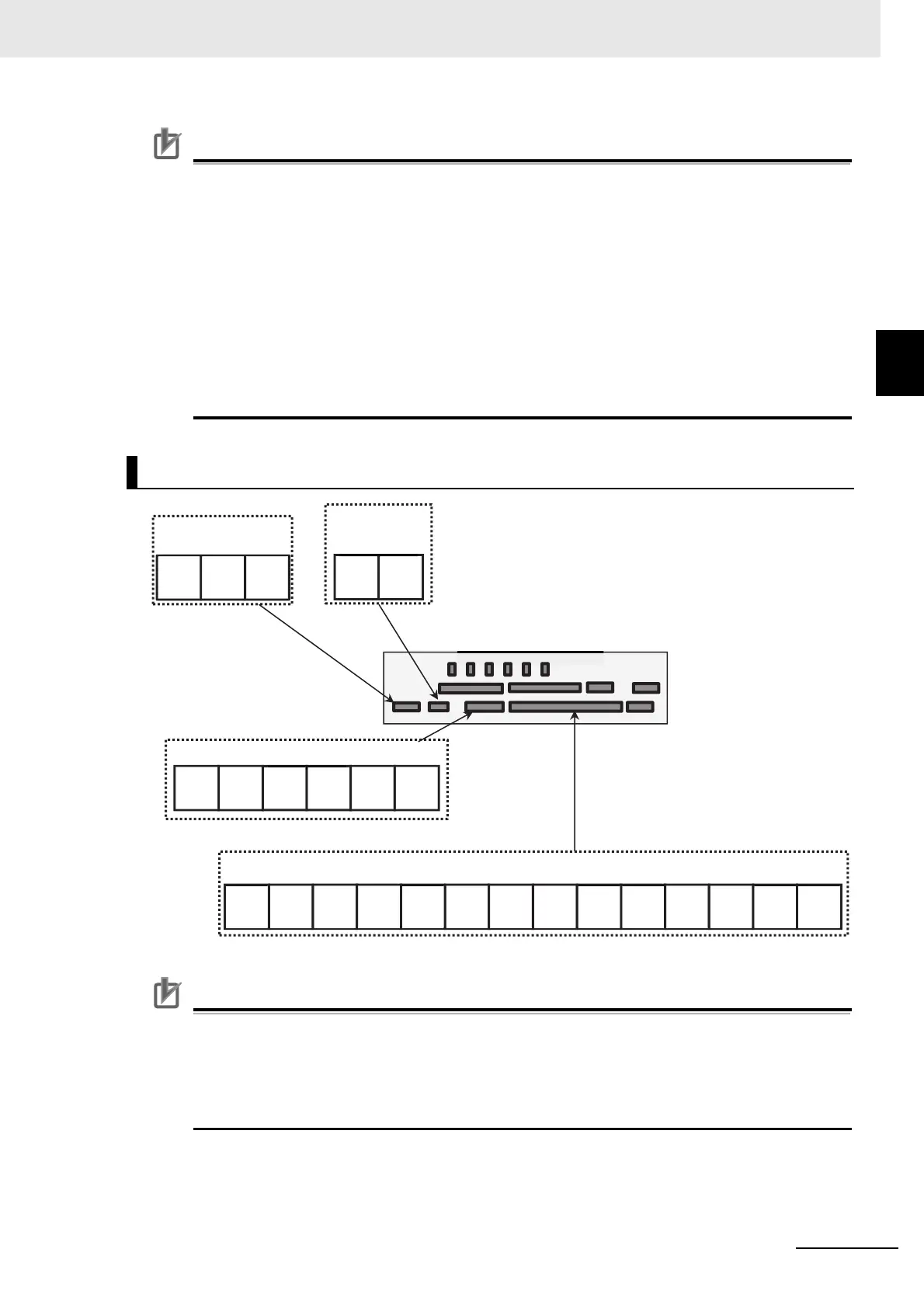
2-3-3 Arrangement and Function of Control Circuit Terminal Block
Precautions for Correct Use
• Using a switch under power-on condition may cause failure. Use the switch only after turning
off the power and confirming that the POWER lamp on the operator keypad is off.
• The factory default setting is shown below. If the switch status does not match the actual
input and output specifications, it may cause failure. Make sure to check that input and output
to be used and switch characteristics are the same.
Analog input terminal settings: Ai1 (SW1) = Voltage input (10 V),
Ai2 (SW2) = Current input (20 mA)
Analog output terminal settings: Ao1 (SW3) = Voltage output (10 V),
Ao2 (SW4) = Current output (20 mA)
Switches power supply method of I/O terminal: P.SEL (SW5) = External power supply (EX)
Switches I/O terminal sink/source: SRC/SINK (SW6) = Source (SRC)
[ ] indicates the factory default setting.
Precautions for Correct Use
• You can switch between the sink/source logic of input terminal by SW6
• When connecting contacts to control circuit terminals, use a relay that does not generate
contact failure even at weak current or voltage emitted from cross-bar twin contacts.
• When connecting a relay with output terminals, connect a diode for absorbing surge in paral-
lel with the coil. Otherwise, internal elements may burn.
Wiring Portion under Control Circuit
16: [ZS]
AL:[AL]
1
[RS]
2
[SCHG]
3
[JG]
4
[FRS]
5
[2CH]
6
[CF1]
7
[CF2]
8
[RV]
9
[FW]
A
[EXT]
B
[USP]
COMCOMCOM
16A 16C
11
[RUN]
12
[FA1]
13
[FA2]
14
[IRDY]
15
[OL]
CM2
AL2 AL1 AL0
Alarm relay output
terminal
Relay output
terminal
Output terminals
Control circuit terminal area
Input terminals