Appendices B STO Function
B - 6
High-function General-purpose Inverter RX2 Series User’s Manual
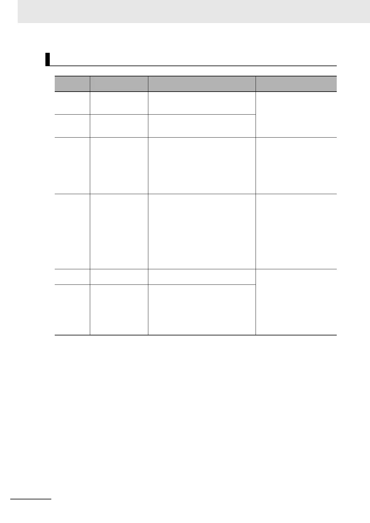
Terminal Specifications
Terminal
symbol
Terminal name Description Electrical characteristics
P24S
24 V output terminal
(for STO input only)
A 24 VDC power supply for contact sig-
nals dedicated for ST1/ST2 terminals.
The common terminal is CMS.
Maximum output current:
100 mA
CMS
24 V output terminal
common (for STO
input only)
A common terminal for 24 VDC power
supply for contact signals dedicated for
ST1/ST2 terminals.
STC
Input logic switching
terminal
A logic switching terminal for STO input.
You can change the input logic changing
the connecting point of short-circuit line.
When an external power supply is used,
remove the short-circuit line and use this
terminal as the input common for
ST1/ST2.
Short-circuit line: Connect
between CMS and STC
ST1/ST2 STO input terminal An input terminal of STO.
Voltage between ST1 and
STC/ST1 and STC
• ON voltage: Min.15 VDC
• OFF voltage Max. 5 VDC
• Maximum allowable voltage
27 VDC
• Load current 5.8 mA
(at 27 VDC)
Internal resistance: 4.7 kΩ
ED+
EDM signal output
terminal (+)
A plus terminal of EDM signal (STO sta-
tus monitoring).
Open collector output
• Between ED+ and ED-
• Voltage drop at ON: 4 V or
less
• Maximum allowable volt-
age: 27 V
• Maximum allowable current:
50 mA
ED-
EDM signal output
terminal (-)
A minus terminal of EDM signal (STO sta-
tus monitoring).