2 Design
2 - 72
High-function General-purpose Inverter RX2 Series User’s Manual
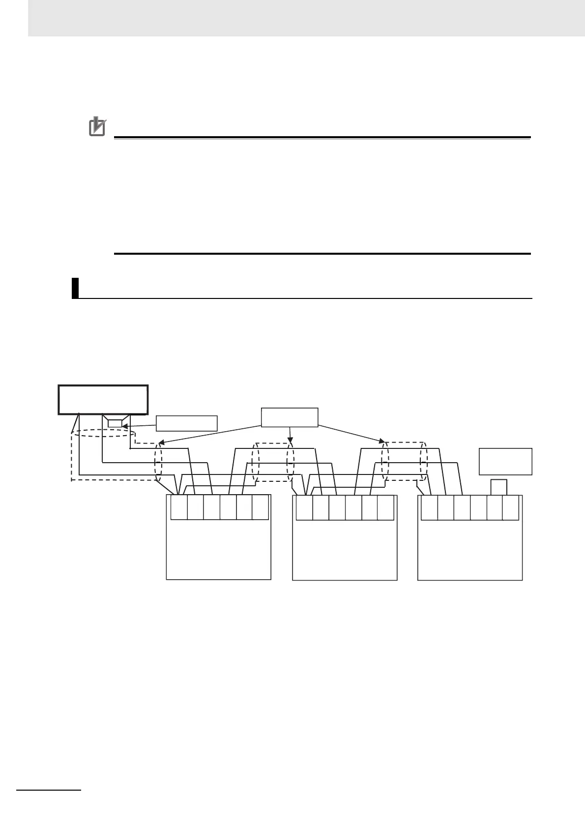
Wiring Method
Connect the communication wire to the control circuit terminal block.
Precautions for Correct Use
• Separate signal lines for control from the main circuit cable and other power supply/power
lines when wiring.
• Do not solder the wire ends. Doing so may result in a contact failure.
• When pin terminals are not used, the wire strip length must be approximately 5.0 mm.
• Connect the shielded wire to the terminal CM1 (frequency reference common) of the
3G3RX2 Series. Do not connect it to the controller.
• Insulate the cable shielded wire with tape or some other means to prevent them from contact
with other signal lines or equipment.
Connect each inverter in parallel as shown below.
For the terminating inverter, short-circuit between terminals RP and SN.
When you connect only one inverter, also short-circuit between terminals RP and SN.
For this inverter, the built-in terminating resistor (100Ω) can be connected by shorting the terminals PR
and SN.
Terminating Resistor Installation
SG
-
+
SP
SN
SP
SN
CM1
RP
SP
SN
SP
SN
CM1
RP
SP
SN
SP
SN
CM1
RP
Shield
External control
equipment
Termination
resistor
Inverter
Termination
resistor
enabled
Inverter Inverter

 Loading...


