2 Design
2 - 74
High-function General-purpose Inverter RX2 Series User’s Manual
Terminal
code
Terminal name Description Electronic characteristics
P24S
24-V Output terminal
(dedicated for STO
input)
24-VDC power supply for contact signals
dedicated for ST1/ST2 terminal. Common
is CMS.
Maximum output current is 100
mA
CMS
24-V output terminal
common (dedicated
for STO input)
Common terminal of 24-VDC power sup-
ply for contact signals dedicated for
ST1/ST2 terminal
STC
Input logic switching
terminal
This is a STO input logic switching termi-
nal.
The input logic can be changed by
changing the position of short bar.
In case of using external power supply,
remove short bars and then it is used as
ST1/ST2 input common.
<at sink logic>
Short bar: connect between
P24S and STC.
<at source logic>
Short bars: connect between
CMS and STC.
ST1/ST2 STO input terminal Input terminal of STO
Voltage between
ST1-STC/ST2-STC
• ON voltage 15 VDC min.
• OFF voltage 5 VDC max.
• Maximum allowable voltage
27 VDC
• Load current 5.8 mA (at 27
VDC)
Internal resistance: 4.7 kΩ
ED+
EDM signal output
terminal (+)
+ side terminal of EDM signal (STO sta-
tus monitor)
Open collector output
• Between ED+/ED-
• Voltage depression 4 V or
below at ON
• Maximum allowable voltage
27 V
• Maximum allowable current
50 mA
ED-
EDM signal output
terminal (-)
- side terminal of EDM signal (STO status
monitor)
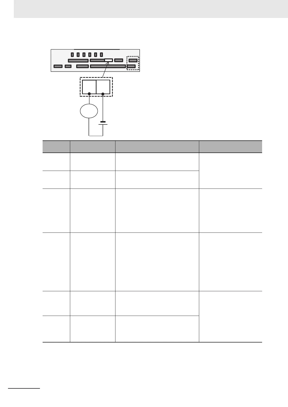
EDM output
Wiring example
Control circuit terminals
Load
 Loading...


