4 Test Run
4 - 8
High-function General-purpose Inverter RX2 Series User’s Manual
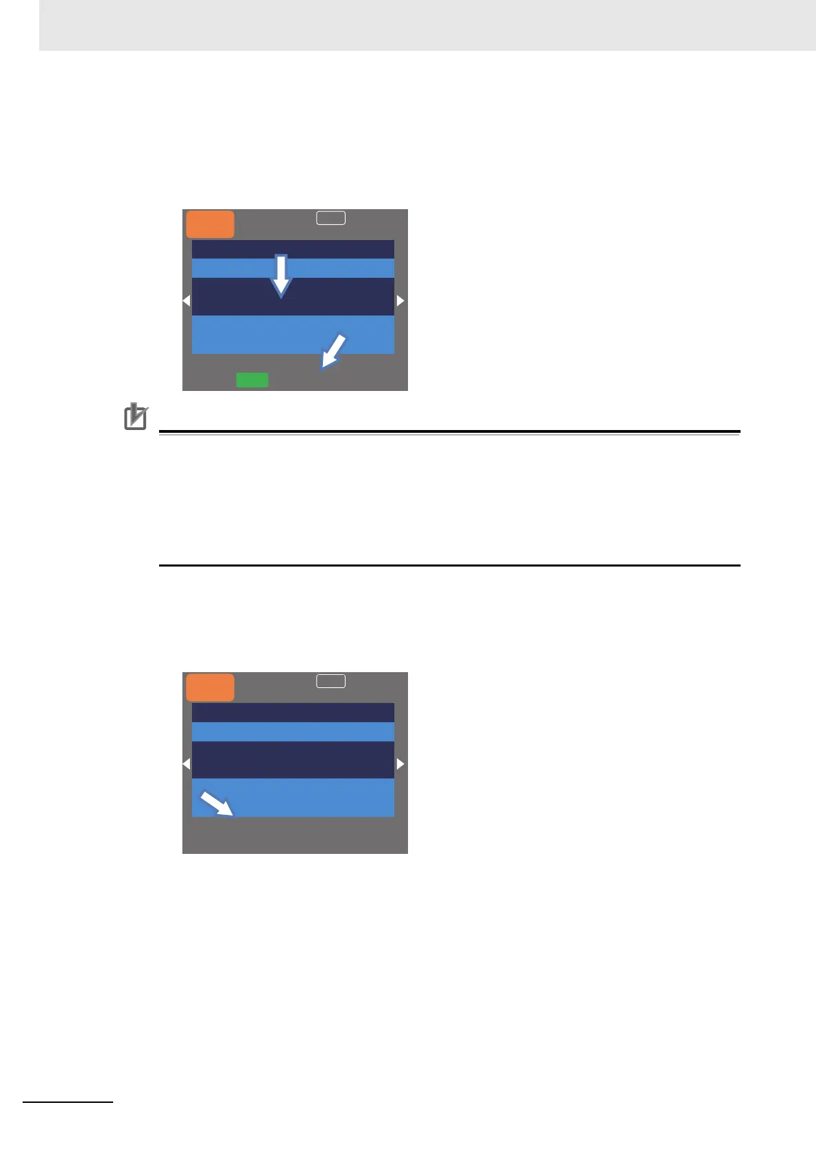
2 Checking the main speed command [FA-01]
When the operation command source is set to “01:Ai1 input”, “Main speed command (Ai1)” will
be shown.
If a frequency command is set in this state, the value will be shown at the bottom command
monitor area.
Precautions for Correct Use
• To connect a cable between Ai1 and L, or between Ai2 and L, make sure to check that a
desired input (voltage or current) is provided to the corresponding positions of DIP switch
SW1 and SW2.
• A damage may be caused by inputting a wrong voltage or current due to wrong selection of
switches, input beyond the specified range (P24 terminal of 24 V is used instead of H termi-
nal of 10 V), and wrong wiring (voltage/current being input reversely due to wrong wire con-
nection or a cable between H and L is short-circuited at 0 Ω during wiring of a tab and so on).
3 Operation command source selection [AA111]
When the operation command source is set to “00:[FW]/[RV] terminal”, the display will disap-
pear from the area for displaying function of RUN key on LCD operator at the bottom.
Note Normal/reverse rotation can be set at [FW]/[RV] terminal.
Menu
Option
60.00Hz
oFW
STOP
M1
H03
Output Frequency
0.00 Hz
FA-01
Main speed command (Ai1)
60.00 Hz
Menu
Option
60.00Hz
STOP
M1
H03
Output Frequency
0.00 Hz
AA111
First operation command selection
00:[FW]/[RV] terminal
 Loading...


