8 Applied Settings
8 - 130
High-function General-purpose Inverter RX2 Series User’s Manual
When [CE101] = 01
Parameter
Item Parameter Data Description
Default
data
Output terminal func-
tion selection 11-15
[CC-01] to
[CC-05]
033
034
033 [LOC]: Low current signal 1 is output.
034 [LOC2]: Low current signal 2 is output.
OFF: Less than or equal to the low current
signal level
ON: More than or equal to the low current
signal level
-
Relay output terminal
function selection
16A-16C
[CC-06] -
Relay output terminal
function selection
AL1-AL0/AL2-AL0
[CC-07] -
Low current signal out-
put mode selection,
1st motor
[CE101]
00 Valid in operation
01
01 Valid only in constant speed operation
Low current detection
level 1, 1st motor
[CE102]
(0.0 to 2.0) x
inverter rated
current
*1
*1. On the parameter about the current and the voltage, the figures and the units to be handled vary in the setting
path.
1) Operator or CX-Drive: 0.1A or 0.1V (When CX-Drive is operated, set [CF-11] Resister data selection to 00
(A,V). When the data of [CF-11] Resister data selection is not set to 00 (A,V), it is not set or displayed cor-
rectly.)
2) Modbus: The current and the voltage vary, depending on the setting of Resister data selection [CF-11].
When [CF-11] Resister data selection is set to 00 (A,V), 0.1A, 0.1V
When [CF-11] Resister data selection is set to 01 (%), 0.01% (Rated ratio)
3) Drive programming: 0.01% (Rated ratio)
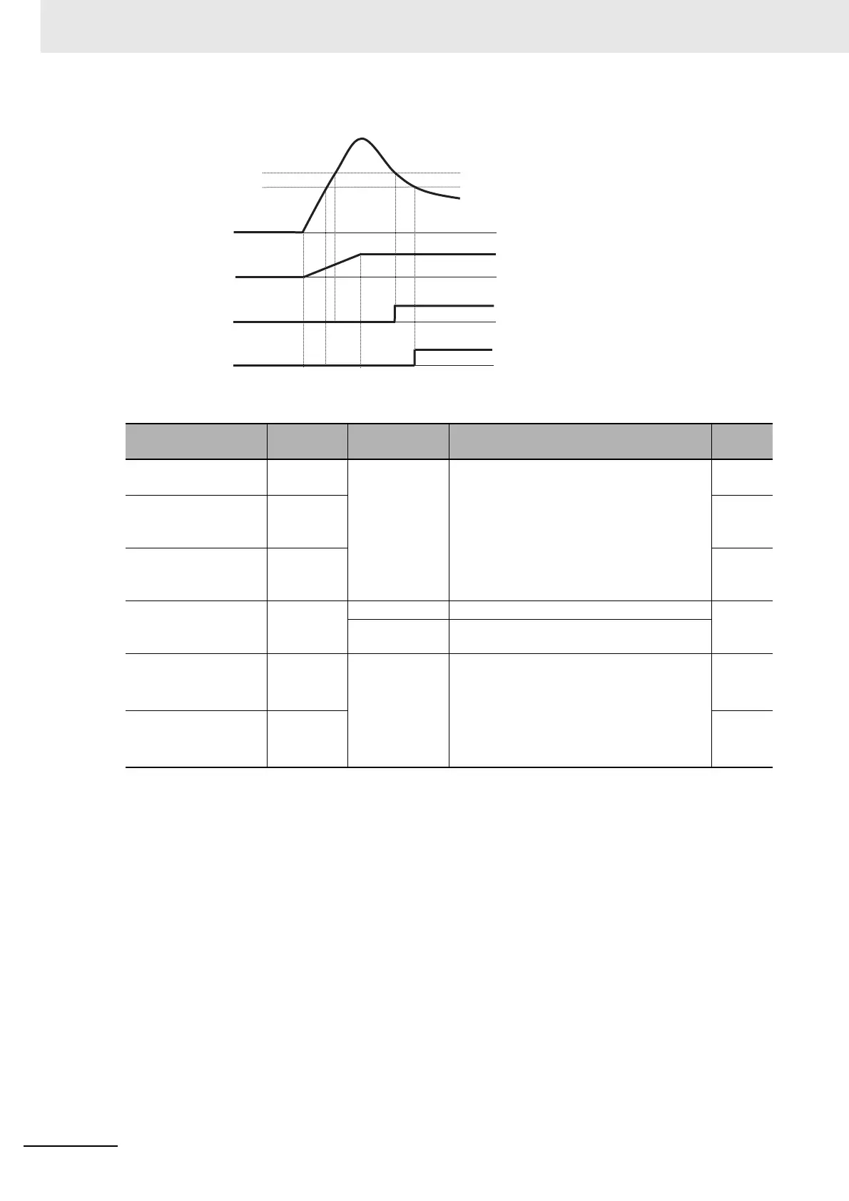
Specify the current level at which the low
current prewarning signal is output.
The signal will be output when the current
becomes lower than the low current pre-
warning detection level.
1.0×
Inverter
rated
current
Low current detection
level 2, 1st motor
[CE103]
1.0×
Inverter
rated
current
[CE102]
[CE103]
Low current signal level
Output frequency
Output signal
[LOC]
Output signal
[LOC2]
Output current

 Loading...


