2 - 33
2 Design
High-function General-purpose Inverter RX2 Series User’s Manual
2-3 Wiring
2
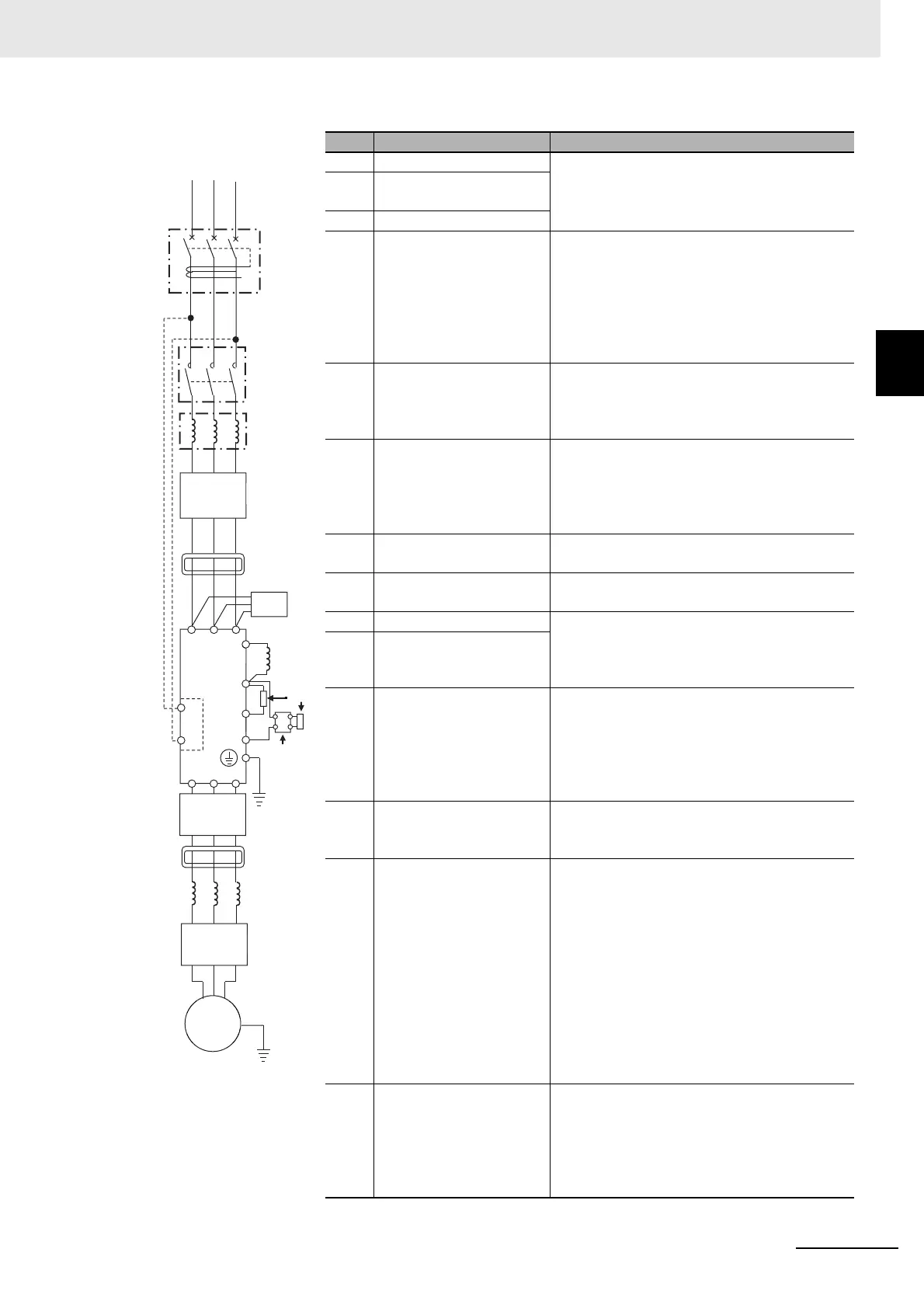
2-3-4 Wiring for Main Circuit Terminals
No. Name Function
<1> Wire See Recommended Wire Diameter, Wiring
Tools, and Crimping Terminals on page 2-43.
<2> Earth-leakage breaker
(ELB)
<3> Magnetic contactor (MC)
<4> Input side reactor This is applied as a countermeasure against
harmonic suppression, or when imbalance of
power supply voltage is 3% or above, or when
power supply capacity is 500kVA or above. It is
also used when a rapid change is made to
power supply voltage. It is also effective in
improving power factor.
<5> Inverter noise filter This reduces the conductive noise that is gen-
erated from the inverter and transferred to the
wire. Connect to the primary side (input side) of
inverter.
<6> Radio noise filter
(zero-phase reactor)
When the inverter is used, noise may be gener-
ated on an adjacent radio or other devices
through wiring on the power supply side. This is
used for reducing the noise (reducing radiation
noise).
<7> Input-side radio noise filter
(capacitor filter)
This reduces the radiation noise that is emitted
from the wire on the input side.
<8> DC reactor This suppresses harmonics generated from the
inverter.
<9> Braking resistor This is used for increasing the braking torque of
inverter, repeating power on and off at high
interval, or reducing the speed of high load
caused by moment of inertia.
<10> Regenerative braking unit
<11> Output-side noise filter This is installed between the inverter and motor
to reduce the radiation noise that is emitted
from the wire. It is used to reduce radio interfer-
ence on radios or televisions or prevent mal-
functioning of measurement instruments and
sensors.
<12> Radio noise filter
(zero-phase reactor)
This is applied for reducing noise generated on
the output side of inverter. (It can be used on
both the input side and output side.)
<13> Output-side AC reactor When a general-use motor is driven by the
inverter, compared with when it is run by com-
mercial power supply, larger vibration may be
generated. By connecting this device between
the inverter and motor, you can reduce the
vibration of motor. Also, if the wiring length
between the inverter and motor is long (10m or
longer), by inserting a reactor, you can prevent
malfunctioning of the thermal relay caused by
harmonic attributable to switching of inverter.
You can also use a current sensor instead of
the thermal relay.
<14> LCR filter This is a filter installed between the inverter
and motor. It improves output current and volt-
age waveform to reduce motor vibration, noise,
and radiation noise emitted from the wire to
convert output-side waveform to sine wave. It is
also effective in suppressing surge voltage.
R S T
R0
T0
U V W
PD
P
N
MM
RB
<1>
<2>
<3>
INV
<4>
<5>
<6>
<7>
<8 >
<9>
<10>
<11>
<12>
<13>
<14>