2 Design
2 - 34
High-function General-purpose Inverter RX2 Series User’s Manual
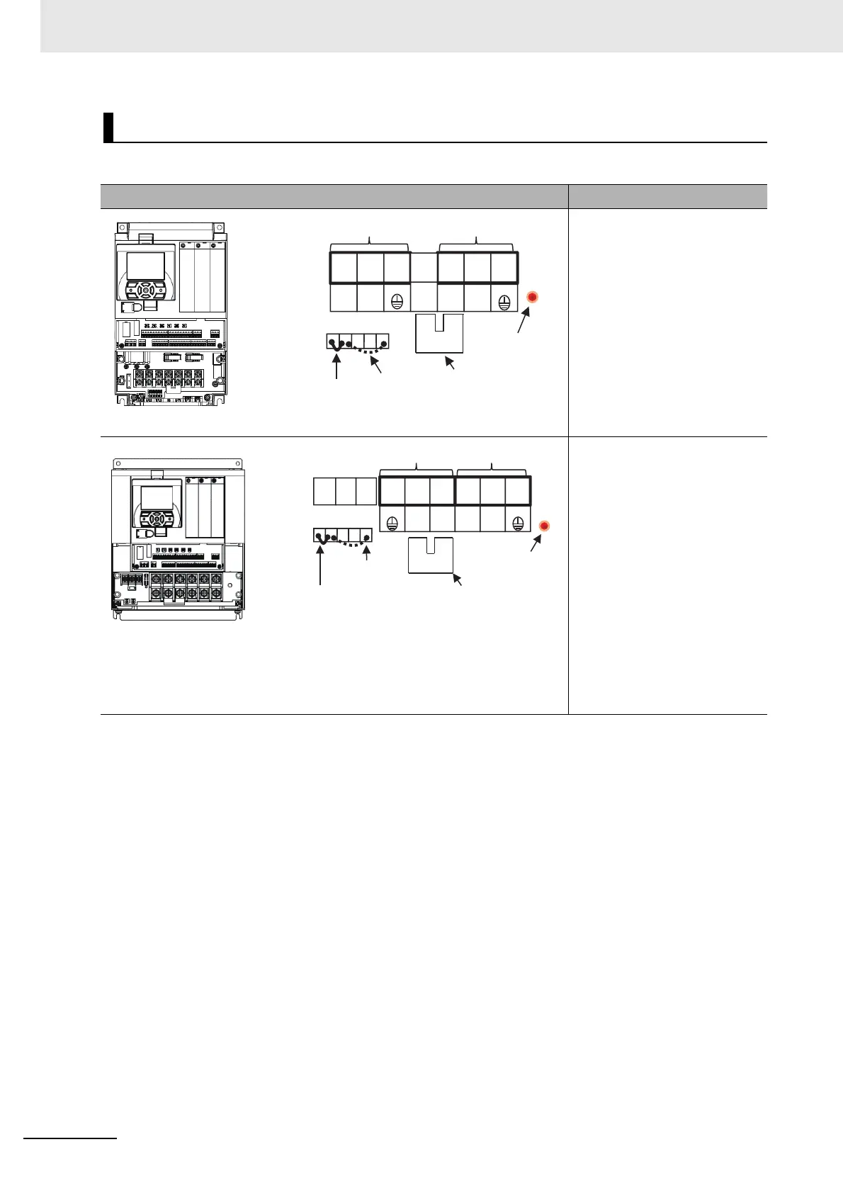
The arrangement of inverters’ main circuit terminals are shown in the following diagrams.
Arrangement of Main Circuit Terminals
Arrangement of Terminals Model
* The EMC filter is enabled/disabled by switching the short bar connector.
3G3RX2-A2004
3G3RX2-A2007
3G3RX2-A2015
3G3RX2-A2022
3G3RX2-A2037
3G3RX2-A4007
3G3RX2-A4015
3G3RX2-A4022
3G3RX2-A4037
R0, T0: M4
Earth terminal: M4
Others: M4
* The EMC filter is enabled/disabled by switching the short bar connector.
3G3RX2-A2055
3G3RX2-A2075
3G3RX2-A4055
3G3RX2-A4075
R0, T0: M4
Earth Terminal: M5
Others: M5
3G3RX2-A2110
3G3RX2-A4110
R0, T0: M4
Earth Terminal: M6
Others: M6
R0
R
(L1)
S
(L2)
T
(L3)
U
(T1)
V
(T2)
W
(T3)
T0
G
P
(+)
N
(-)
G
OFF G ON
RB
(RB)
PD
(+1)
Power supply input wire
EMC filter
disabled
EMC filter
enabled
Motor output wire
PD-P short bar
Charge lamp
(Light when
electricity turned on)
G
R
(L1)
S
(L2)
T
(L3)
U
(T1)
V
(T2)
W
(T3)
R0
PD
(+1)
P
(+)
N
(-)
RB
(RB)
G
T0
OFF G ON
Power supply input wire
EMC filter
disabled
EMC filter
enabled
Motor output wire
PD-P short bar
Charge lamp
(Light when
electricity turned on)
 Loading...


