2 - 45
2 Design
High-function General-purpose Inverter RX2 Series User’s Manual
2-3 Wiring
2
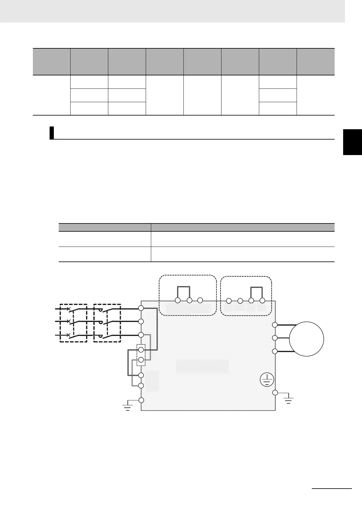
2-3-4 Wiring for Main Circuit Terminals
Wiring of main power supply input terminal, peripherals and others are described here.
Establishing Breakers for Wiring
Connect R, S, T (L1, L2, L3) to the AC power supply.
Connect U, V, W (T1, T2, T3) to the motor.
Driving a 200-Volt motor by a 400-Volt inverter may result in fire.
The input power supply must be in the range shown below:
Installing Earth Leakage Breaker
When selecting the earth leakage breaker to use between the power supply and the main power
supply input terminals (R, S, T), consider the following two points.
High-frequency leakage current from inverter
The inverter produces a high-frequency leakage current due to its high-speed output switching.
B413K
ND
3/0×2
(85.0×2)
1(42.4) - M10
80-10/60-8
10.0 to 12.0/
11.7
(16.5/12.5)
LD
4/0×2
(107×2)
100-10/60-8
VLD
250kcmil×2
(127×2)
150-10/60-8
Wiring of Main Power Supply Input Terminal (R/L1, S/L2, T/L3)
Voltage class Input range
200 V class 200 to 240 VAC (allowable variation range: +10%/-15%)
Power supply frequency 50 Hz/60 Hz (variation range ±5%)
400 V class 380 to 500 VAC (allowable variation range: +10%/-15%)
Power supply frequency 50 Hz/60 Hz (variation range ±5%)
Model
3G3RX2-****
Rated
settings
Power line
AWG (mm
2
)
R,S,T,U,V,W,
P, P D, N
Ground line
AWG (mm
2
)
Braking
resistor AWG
between P
and RB (mm
2
)
Screw size of
power line
terminal
Crimping
terminal
power line/
ground line
Tightening
torque
N•m
ELB MC
R/L1
S/L2
T/L3
R0
T0
U/T1
V/T2
W/T3
MM
3~
P
PD
RB
N
Earth-leakage
breake
Magnetic
contactor
Internal EMC filter
Short bar or terminal
Short bar
3-phase AC motor
Main circuit
terminal area
D-class grounding
(200V class)
C-class grounding
(400V class)
J51 connector
Control circuit
power supply
3-phase
AC
power
supply
Disable Enable
 Loading...


