Pin Number Signal Function Notes
2 SERIAL_IN_RX RS-232 Receive data Data input into unit; ToD message
3 NC No Connection
4 NC No connection
5 GND Ground
Bottom row of 4 pins
6 NC No connection
7 NC No connection
8 NC No connection
9 NC No connection
ASCII Time Code, RS-485 [1204-04]: Specifications
Inputs/Outputs: (1) Input, (1) Output
Signal Type and Connector: (1) RS-485 terminal block for both Input and Output
Accuracy: ±100…1000 µs (format dependent)
Maximum Number of Cards: 6
Ordering Information: 1204-04 ASCII Time Code Module (RS-485)
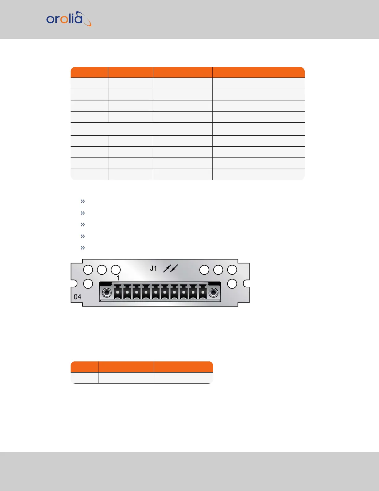
Figure 5-48: Model 1204-04 option card rear plate
Pin Assignments
Table 5-21:
Pin-out, RS-485 terminal block connector J1
Pin No. Signal Function
1 (left) SERIALTX_RS485+ + RS-485 data output
SecureSync 2400 User Manual 449
APPENDIX