complete a circuit, depending on whether the relay is energized/de- energized and
whether the custom alarm circuit is connected to the NO or NC contacts.
To use this option card to provide an audible indication of a Minor or Major alarm being
asserted, SecureSync does not pass or generate an audible tone. It is just the switch that
allows the tone to be generated. Or for a visible alarm indication, the three relays can allow
DC voltage to be routed to the light, when an alarm is asserted.
The best way to think of each of the alarm relays is that they are simply a light switch on the
wall. When the switch is off (relay is in one position) the light/buzzer is off. But if you
toggle the switch (relay) to the other position (either a Minor or Major alarm is alarm is asser-
ted), the light/buzzer comes on. When a Minor or Major Alarm is asserted, the applicable
relay(s) switches states. This can then allow a custom circuit to be able to sound an alarm or
to illuminate a light, as desired.
The nominal switch capacity is 30V, 2A (maximums: voltage = 220 VDC, power = 60W,
current = 2A). So you can connect any desired audible//visible device or component to
this relay that can operate within this rating (Spectracom doesn't make any specific recom-
mendations on what visible or audible alarms to use in conjunction with this Option Card).
Further below is a diagram of ways that a light or buzzer can be connected to any of the
three relays on this Option Card.
Note that any necessary wiring, the light/buzzer and the power source (labeled in the dia-
gram above as “DC Power Supply”) for the light/buzzer is supplied by the customer.
“Relay 1”, “Relay 2” and “Relay 3” represent the three available relays. The three tables on
the left provide the pin-outs for each of the relay contact closures.
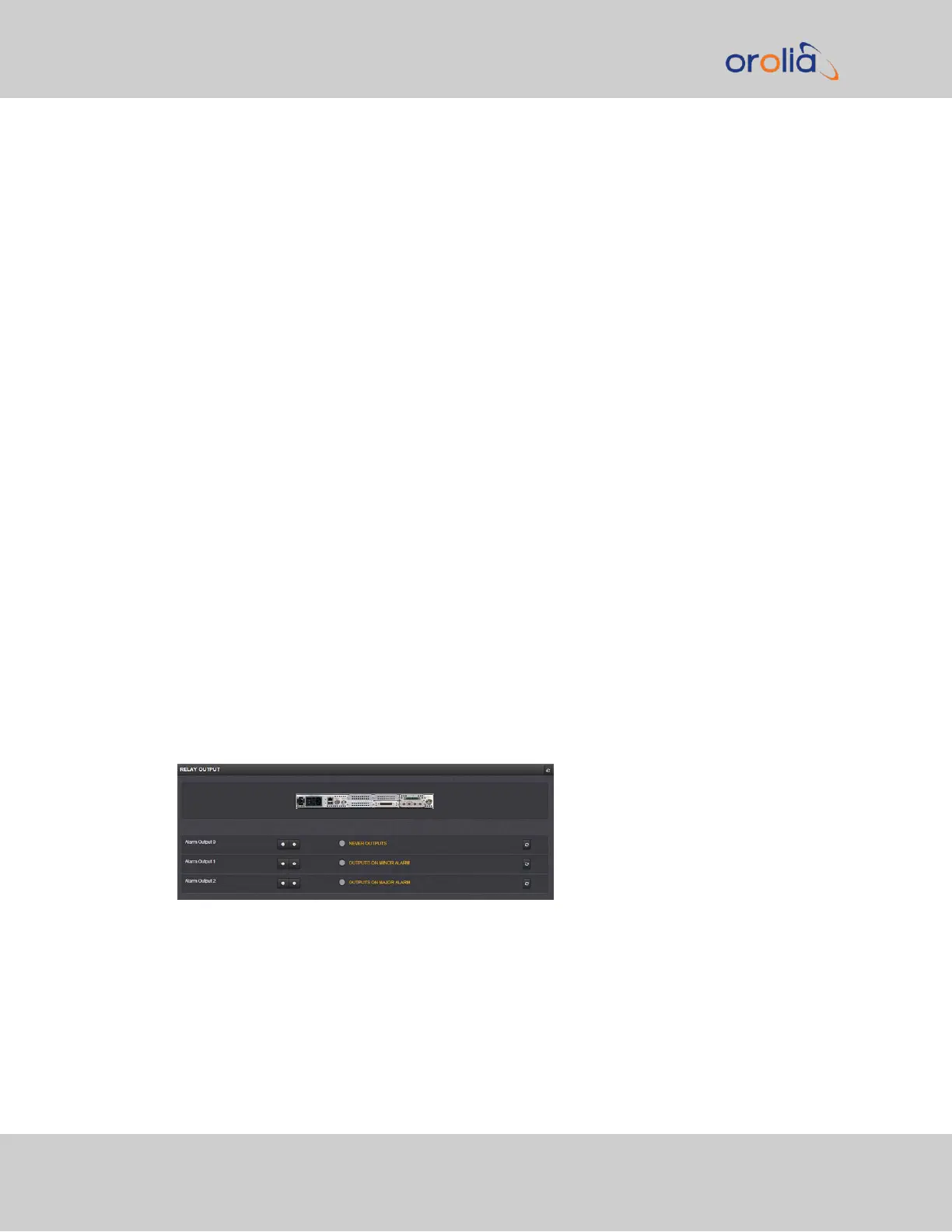
Alarm Relay Output: Viewing Signal State
To quickly view the signal state of all three alarm outputs, see: "Viewing an Input/Output
Signal State" on page337.
Each alarm output will be in one of these 3 states:
490 SecureSync 2400 User Manual
APPENDIX