Figure 5-55: Contact closure relay pinouts
1.
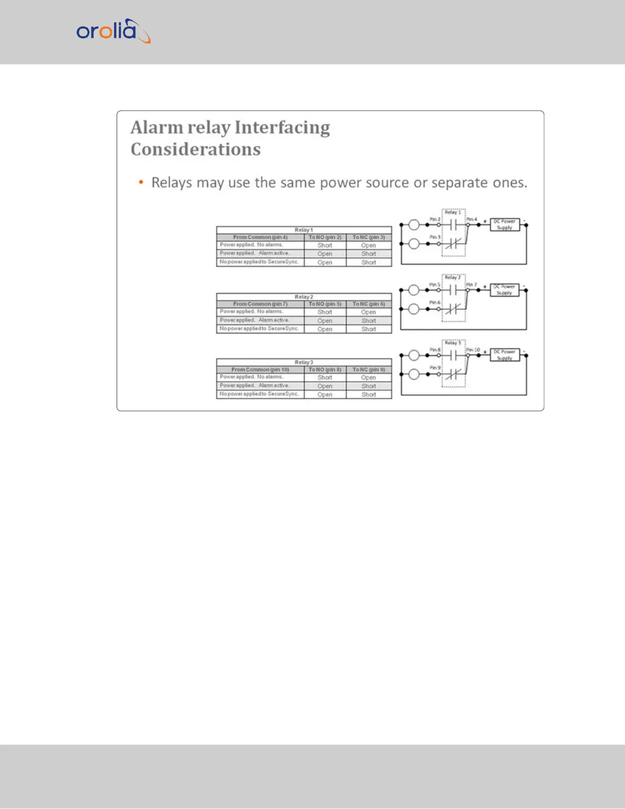
All relay contacts are labeled as in their de-energized state (power removed or alarm
asserted).
2.
The "normal" state of the relays (no alarms asserted) is relays energized.
3.
The applicable relay(s) (Minor or Major, as configured in the browser) is /are de-ener-
gized when a Minor or Major alarm is asserted.
4.
Both the Minor and Major alarms are active (relays de-energized and in their alarm
state) when input power is removed from SecureSync.
5.
For information on how to configure the relays as either a Minor alarm relay or a
Major alarm relay, see "Alarm Relay Output: Edit Window" on page491.
Each of the three available relays on this option card can be configured to be either a Minor
or a Major alarm relay. The three relays are dry contact closures that can either open or
SecureSync 2400 User Manual 489
APPENDIX