SECTION 05: COOLING SYSTEM
DOB 1300-1556 | X3-45 Commuter PA-1648 Maintenance Manual First release Oct 2020
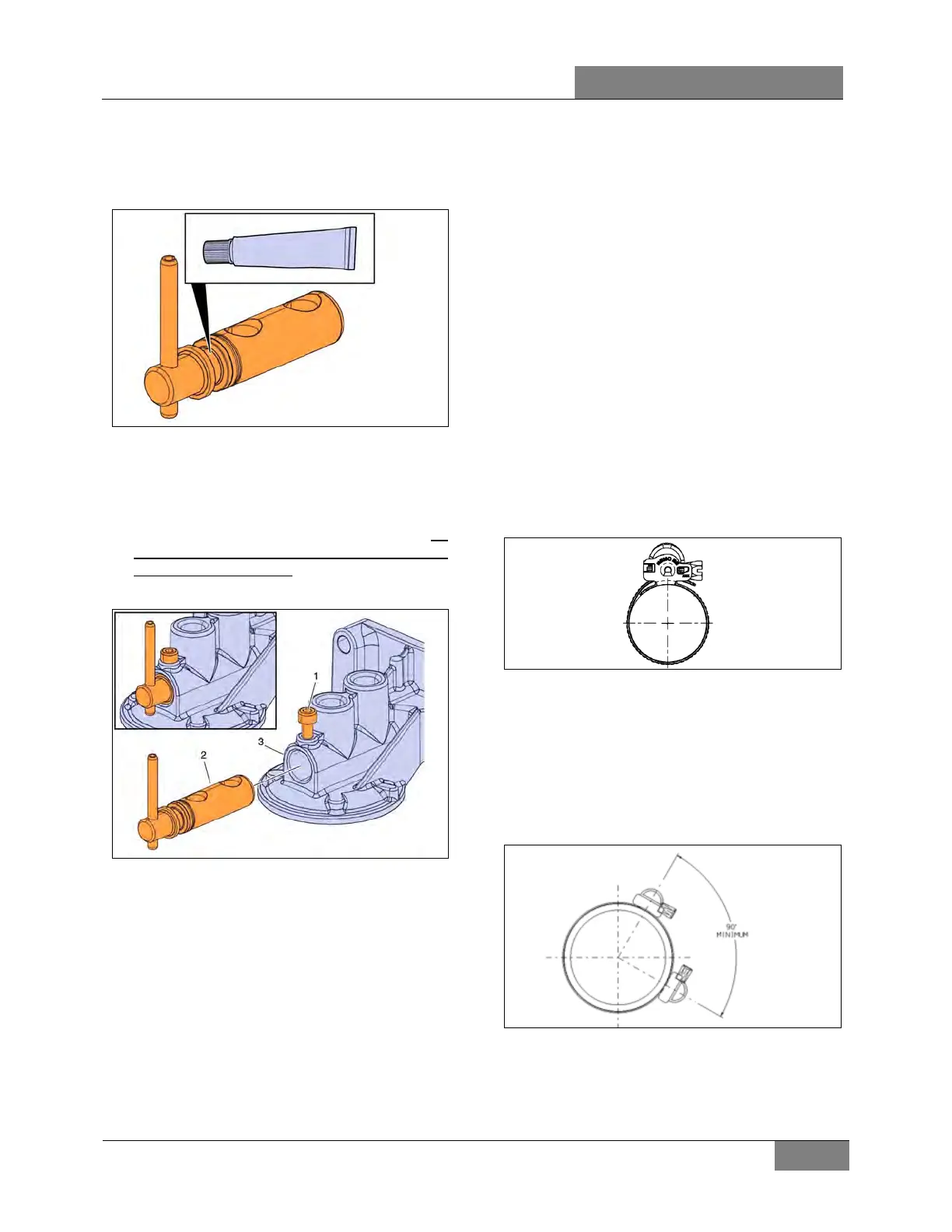
10. Apply grade NLGI No.2 silicone-based
grease to the grooved area of the spindle.
Ensure the grooved area of the spindle is
filled as completely as possible (Figure 9).
FIGURE 9: APPLY GRADE NLGI NO.2 SILICONE-BASED
GREASE TO THE GROOVED AREA
11. Reinsert the spindle (2) into the coolant filter
housing (3) and tighten the M5 hex socket
screw (1) (Figure 10).
12. To prevent reoccurrences, at a minimum, the
grease should be repacked in this area when
the coolant is changed, and the valve should
be rotated periodically.
FIGURE 10: INSERTING THE SPINDLE
13. Fill the cooling system with the recommended
coolant.
14. Set the engine stop/ignition interlock back to
the normal position.
15. Start the engine, check for leaks and proper
operation.
16. After shutdown, replenish coolant as
necessary.
4. HOSES
Rotten, swollen, and worn out hoses or loose
connections are frequent causes of cooling
system problems.
Serious overheating is often caused by an old
hose collapsing or from rotten rubber shedding
from hoses and clogging the coolant passages.
Connections should be inspected periodically
and hose clamps tightened. Replace any hose
found to be cracked or swollen.
4.1 HOSE CLAMPS ON COOLANT LINES
All hose clamps used for the heating and cooling
systems have a spring function (spring in the
housing) to compensate for the normal
expansion/contraction of hose and metal
connection that occurs during vehicle operation
and shutdown. These clamps are worm-driven
and made of stainless steel (Figure 11).
FIGURE 11: CLAMP TYPE USED ON HEATING &
COOLING SYSTEMS
All connections equal or greater than 2 inches
OD have doubled clamps (two clamps, side by
side) with screw housing separated from at least
90°. A torque wrench should be used for proper
installation (Figure 12 & Figure 13).
TORQUE: 30 lb-in (3.39 Nm)
FIGURE 12: DUAL CLAMP MINIMUM SPREAD ANGLE
 Loading...


