DOB 1300-1556 | X3-45 Commuter PA-1648 Maintenance Manual Section 06 revised release October 2021
9.3 BATTERY DISCHARGE PROTECTION
To prevent discharge of the batteries when the
engine in not running, some functions are
automatically switched off if the batteries voltage
drops below 24.4 volts for more than 30
seconds. The "Battery Voltage Warning"
pictogram will show on the DID. Set the ignition
key to the OFF position and then turn the
ignition key to the ON position to reactivate the
functions for a period of 30 seconds before they
switch off again.
If a prolonged use of the functions with the
engine not running is necessary, connect the
battery to a charger.
9.4 MAIN ELECTRICAL SHUT-OFF SWITCH
Main 12-volt and 24-volt battery (master) relays
are provided for this vehicle. The relays are
located in the main power compartment. The 24-
volt battery relay R1 & 12-volt battery relay R3
engage when ignition key is in the ON or ACC
position and the main electrical shut-off switch
is set to the ON position.
When the main electrical shut-off switch is set to
the OFF position, the main battery relays R1 &
R3 disengage thus all electrical supply from the
batteries to main circuit breakers CB1, CB3,
CB5, CB8, CB10, CB11, CB13, is cut off, with
the exception of the following items, among
others.
• Main circuit breakers CB2, CB6, CB9 which
are directly connected to the batteries;
• Battery equalizer check module;
• MCM;
• ECM;
• TCM (Allison transmission);
• Aftertreatment Control Module (ACM);
• Preheater electronic timer;
• Preheater and water recirculating pump;
• Entrance door;
• Radio memory;
• Fire suppression system (momentarily);
• Horn, Hazard:
• Wheelchair lift system;
• Cluster memory.
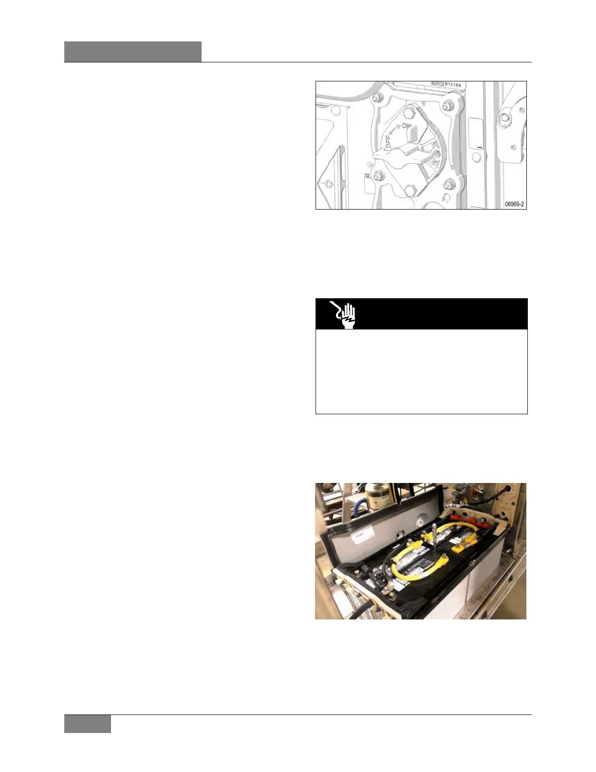
FIGURE 30: MAIN ELECTRICAL SHUT-OFF SWITCH
9.5 BATTERY REMOVAL AND
INSTALLATION
The batteries are located in the R.H. side of the
engine compartment.
DANGER
To prevent possible electric shocks or
sparking, the main electrical shut-off switch in
the R.
H. side of the engine compartment
(Figure 30) should be in the "Off" position
before disconnecti
batteries. In addition, trip main circuit breakers
CB2 & CB6.
Battery Removal
1. Remove the battery bank cover and place
behind the battery bank (Figure 31).
FIGURE 31: BATTERY BANK COVER REMOVED
2. Disconnect the ground cable first (Figure 32).
 Loading...


