SECTION 12: BRAKE AND AIR SYSTEM
DOB 1300-1556 | X3-45 Commuter PA-1648 Maintenance Manual Section 12 revised Jan 2021
2. AIR SYSTEM
The basic air system consists of an air
compressor, tanks, valves, filters and
interconnecting lines and hoses. It provides a
means for breaking, operating controls and
accessories and suspension (refer to Section
16, "Suspension", for complete information on
suspension description and maintenance). An
air system schematic diagram is annexed in the
technical publications box provided with the
vehicle for better understanding of the system.
3. BRAKES
This vehicle uses both the service brake and
emergency/parking brake. The service brake air
system is divided into two independent circuits
to isolate front brakes from rear brakes, thus
providing safe braking in the event that one
circuit fails. Front axle brakes operate from the
secondary air system, while brakes on both the
drive axle and tag axle operate from the primary
air system.
The tag axle service brake operates only
when the axle is in normal ride position
(loaded and down).
Furthermore, the brake application or release,
which is speed up by pneumatic relay valves (R-
14), will start with the rear axles and will be
followed by the front axle, thus providing uniform
braking on a slippery road. The vehicle is also
equipped with an Anti-Lock Braking System
(ABS), which is detailed later in this section.
The drive is provided with spring-loaded
emergency/parking brakes, which are applied
automatically whenever the control valve supply
pressure drops below 60 psi (413 kPa). The
emergency/parking brake overrule system allows
the driver to release spring brakes, and to move
the vehicle to a safe parking place, such as in
the case of a self-application of these brakes
due to a drop in air pressure.
4. AIR TANKS
The air coming from the compressor is first
forwarded to the ping tank, then to the Haldex
condenser-separator, the air dryer, the wet air
tank, the primary (for the primary brake system),
secondary (for the secondary brake system),
and accessory (for the pneumatic accessories)
air tanks.
Two additional air reservoirs are installed on the
vehicle: the kneeling air tank and the parking
brakes overrule air tank.
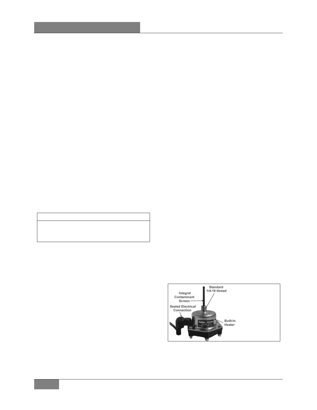
4.1 WET TANK AUTOMATIC DRAIN VALVE
The wet tank automatic drain valve (Figure 1) is
designed to remove liquids from the wet tank
each time the brake is applied as the solenoid is
connected to the stop light circuit. A built-in
heater prevents freeze-ups and keeps the air
system clean in all temperature.
4.1.1 Installation
1. Make sure that there is no pressure in the
wet tank (emptied tank).
2. Fit the automatic drain valve to the wet tank.
Tighten valve finger tight and then tighten
an additional 1 ½ turns, do not over tighten.
3. Connect the power cable to the valve
connector.
4. Charge the air system and make sure there
is no leakage. Also check functioning of the
drain valve by applying the service brake.
FIGURE 1: WET TANK AUTOMATIC DRAIN VALVE
 Loading...


