SECTION 09: PROPELLER SHAFT
DOB 1300-1556 | X3-45 Commuter PA-1648 Maintenance Manual (Draft Version – April 2020)
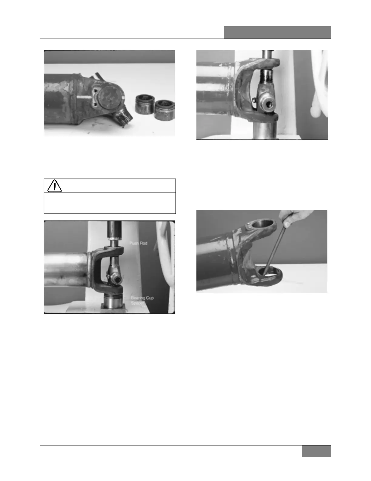
FIGURE 17: INCORRECT POSITIONING
3. Using an arbor press, press down on the
upper bearing cup assembly until the
shoulder of the journal cross makes contact
with the inside of the yoke ear.
DO NOT over press the bearing cup and
journal cross. This can damage the inside of
FIGURE 18
4. The bearing cup is not designed to drop out
of the yoke. Move the partially pressed-out
bearing cup from side to side, to "walk" the
bearing cup out of the yoke ear. Remove the
bearing cup from the trunnion.
5. Place the yoke in the press, with the
remaining bearing cup face down. Using a
push rod, press on the end of the journal
cross trunnion. Continue to press down on
the journal cross trunnion until the shoulder
of the journal cross makes contact with the
inside of the yoke ear.
FIGURE 19
5.2.1 Inspect Tube Yoke and Flange Yoke (If
Applicable)
1. Inspect the tube yoke and flange yoke (if
applicable) cross hole surfaces for damage
or raised metal. Raised metal or fretting can
be removed from yoke cross holes with a
fine-toothed file and/or emery cloth.
FIGURE 20: RAISED METAL OR FRETTING CAN BE
REMOVED FROM YOKE CROSS HOLES WITH A FINE-
TOOTHED FILE
5.3 REMOVAL PROCEDURE FOR SLIP
MEMBER BOOT
1. It is imperative to mark all mating
components of the propeller shaft. Mark the
propeller shaft with a marking stick, paint
marker or other legible marking device.
2. Remove and discard both boot clamps.
Clamps may be separated using a chisel to
disengage locking hooks. DO NOT reuse
clamps.
 Loading...


