DOB 1300-1556 | X3-45 Commuter PA-1648 Maintenance Manual First release Oct 2020
3.2.1 Inspection
Loosen lower mounting of both shocks, and then
carefully attempt to raise and lower the bottom
portion of each shock. Note the rate of effort for
distance of travel. Replace both shocks if a
definite differential rate is found.
The shock must be bench checked in an upright,
vertical position. If checked in any other position,
air will enter the cylinder tube and make the
shock absorber appear defective.
Proceed as follows to check shock absorbers:
1. With the shock absorber in a vertical position
(top end up), clamp the bottom mount in a
vise.
CAUTION
Do not clamp the reservoir tube or the dust
tube.
2. Rotate the dust tube. Notice any binding
condition (may be compared with new unit).
Binding condition indicates a scored rod.
Units with scored rods should be replaced.
3. Fully extend shocks and check for leaks in
the seal cover area. Shock fluid is a very thin
hydraulic fluid that has a characteristic odor
and dark brown tint. A slight trace of shock
fluid around the seal cover area is not a
cause for replacement (Refer to the SACHS
document “Guideline to Evaluate Warranty
Claims” annexed at the end of this section
before replacing a shock). The shock seal is
designed to permit a very slight seepage to
lubricate the rod. Units that leak should be
replaced.
4. Visually check shock for dents that could
cause the shock to bind. Also, check for a
bent rod.
5. Extend and collapse shock several times to
determine that it has control (resistance) in
both rebound and compression.
6. Visually inspect the shock mountings and
vehicle mounting for:
a. Broken mounts;
b. Extreme bushing wear;
c. Shifted bushing or sleeve;
d. Deep cracks in bushing material
(shallow surface cracks are normal);
e. Loose shock absorber pins;
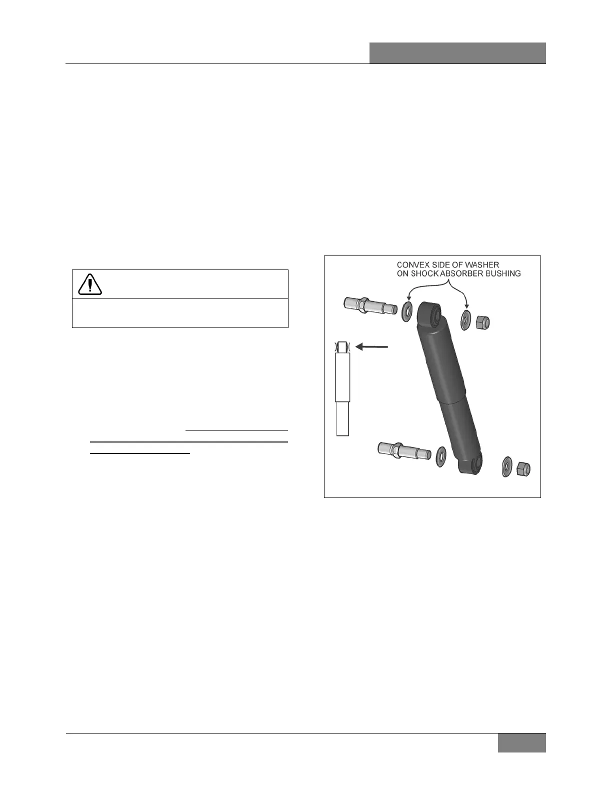
f. Presence of convex washers, and their
position relative to the rubber bushing.
3.2.2 Removal
1. Remove nuts and washers from shock
absorbers on upper and lower mounting
pins, taking care to identify the inner and
outer washers to ease reinstallation. Refer to
Figure 4 for details.
2. Remove the shock absorber assembly from
pins.
3. Remove the two inner bushings from the
shock absorber and discard them.
FIGURE 4: SHOCK ABSORBER 16008
3.2.3 Installation
1. Ensure that the shock absorber mounting
pins are tight and that the threads are not
stripped.
2. Install new rubber mounting bushings on
shock absorbers (upper and lower).
3. Place the inner washers (with washer
convex side facing the shock absorber
rubber bushing) on each shock absorber pin.
4. Install the shock absorber eyes over the
mounting pins, then the outer washers (with
washer convex side facing the shock
absorber rubber bushing) on each shock
extremity.
 Loading...


