DOB 1300-1556 | X3-45 Commuter PA-1648 Maintenance Manual Section 06 revised release March 2021
15.1 HEADLAMPS
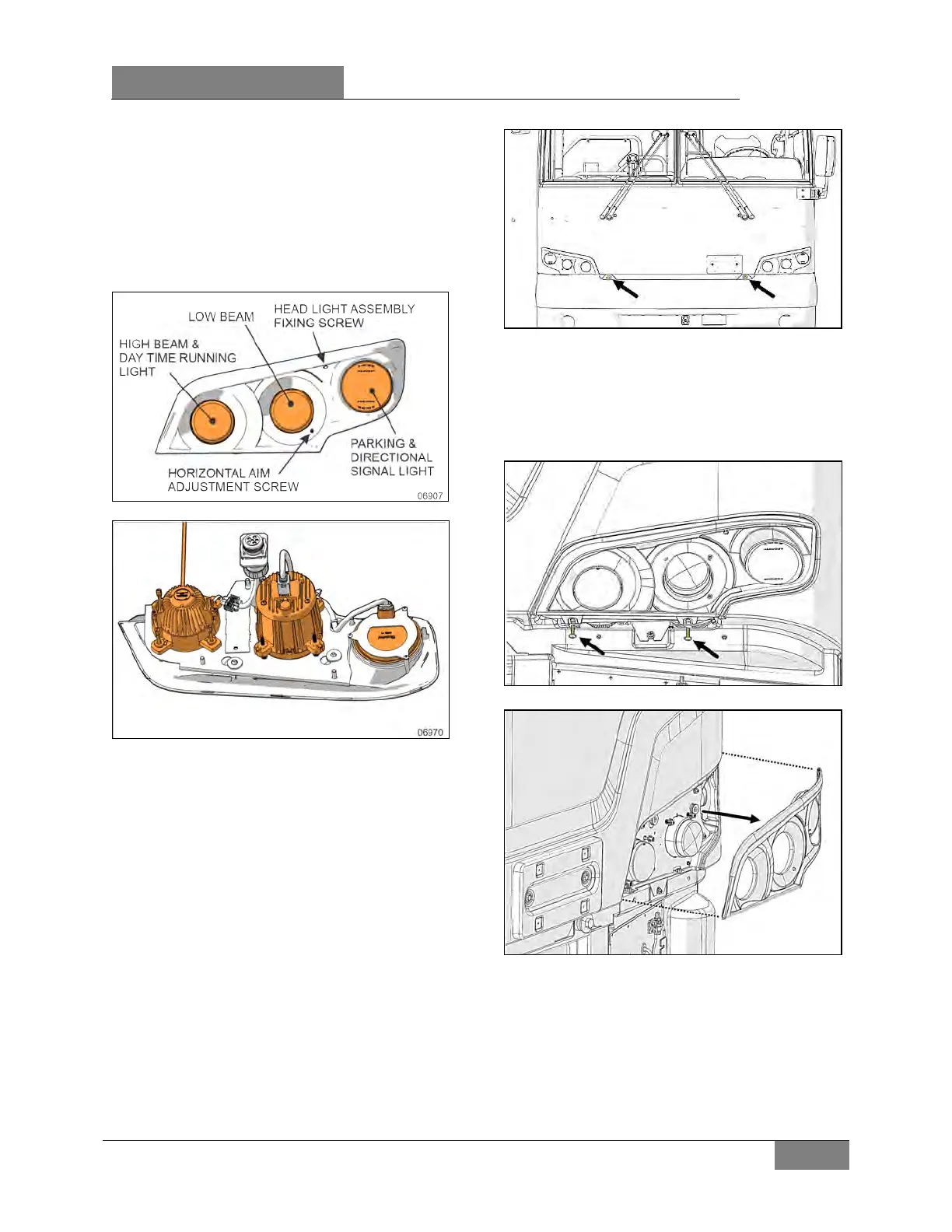
Each headlamp assembly consists of two 90 mm
(3½ inch) LED modules and one 100 mm
(4 inch) 12-volt LED turn signal light (Figure 57).
Middle lamps are used for low beam. Inner
lamps are used for high beam and light intensity
is lower for the daytime running mode.
FIGURE 56: HEADLAMP ASSEMBLY
FIGURE 57: HEADLAMP ASSEMBLY
15.1.1 Maintenance
Clean headlamp assembly with soap and water.
When a headlamp fails, a new module must be
installed. Headlamp modules must be properly
aimed to provide maximum allowable road
illumination. When using mechanical aiming
devices, follow the manufacturer’s instructions.
15.2 LED MODULES AND TURN SIGNAL
MODULE REPLACEMENT
1. Unscrew the 2 bumper retaining bolts shown
on the image (47 lbs-ft).
FIGURE 58: BUMPER RETAINING BOLTS
2. Lower the hinged bumper.
3. Remove the headlights bezel. To do so,
unscrew the 2 Torx screws shown on the
image. Disconnect the directional turn signal
module cable and put the bezel aside.
FIGURE 59: UNSCREW THE 2 TORX SCREWS
FIGURE 60: HEADLAMP ASSEMBLY BEZEL
4. Remove 4 screws holding the headlight
module.
 Loading...


