SECTION 05: COOLING SYSTEM
DOB 1300-1556 | X3-45 Commuter PA-1648 Maintenance Manual First release Oct 2020
3. Remove the fan.
4. Reverse removal procedure to reinstall the
fan and apply specified torque to the fan
frame mounting screws.
TORQUE: 30 lb-in (3 Nm)
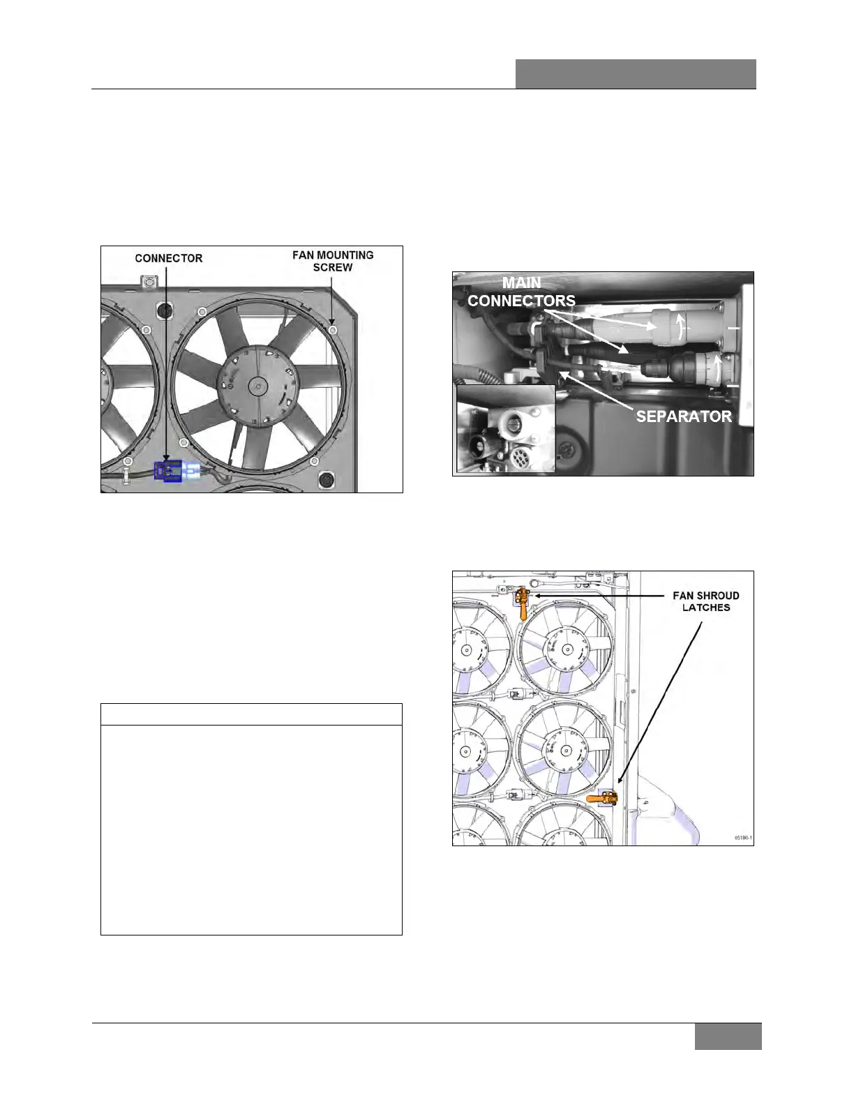
FIGURE 24: CONNECTOR & MOUNTING SCREW
LOCATION
11.3 COOLING FAN SHROUD REMOVAL &
INSTALLATION
1. Open rear engine door and set engine stop
button to the OFF position (push).
2. Open the radiator door and disconnect the
door support arm to allow full door opening
(optional).
If fan shroud is removed in preparation for the
removal of the complete coolin
(see 11.4 in this section);
must be removed from the vehicle.
- Open and support door.
- Disconnect side marker lights.
- Remove light harness from door.
- Unscrew lower hinge from vehicle.
- Lift and remove door.
See section 18 BODY for more information.
3. Disconnect the cooling fans circuit breaker
box (Figure 25).
• Turn the two main harness (black and
red) connectors half a turn
counterclockwise and pull.
• Turn the smaller wiring connector 1/3
turn counterclockwise.
• Remove the wires from the wire
separator and move them out of the
way.
FIGURE 25: CIRCUIT BREAKER BOX CONNECTIONS
4. Unlatch the two shroud hold down latches
and open the shroud assembly (yellow
handle Figure 26).
FIGURE 26: SHROUD HOLD DOWN LATCHES
5. Unfasten the limiter strap at the bottom of
the shroud assembly.
6. Support the bottom of the shroud assembly
with a lift table or other suitable equipment.
7. Unscrew the shroud upper hinge at the
vehicle structure and remove the hinge.
 Loading...


