SECTION 05: COOLING SYSTEM
DOB 1300-1556 | X3-45 Commuter PA-1648 Maintenance Manual First release Oct 2020
11. COOLING ASSEMBLY
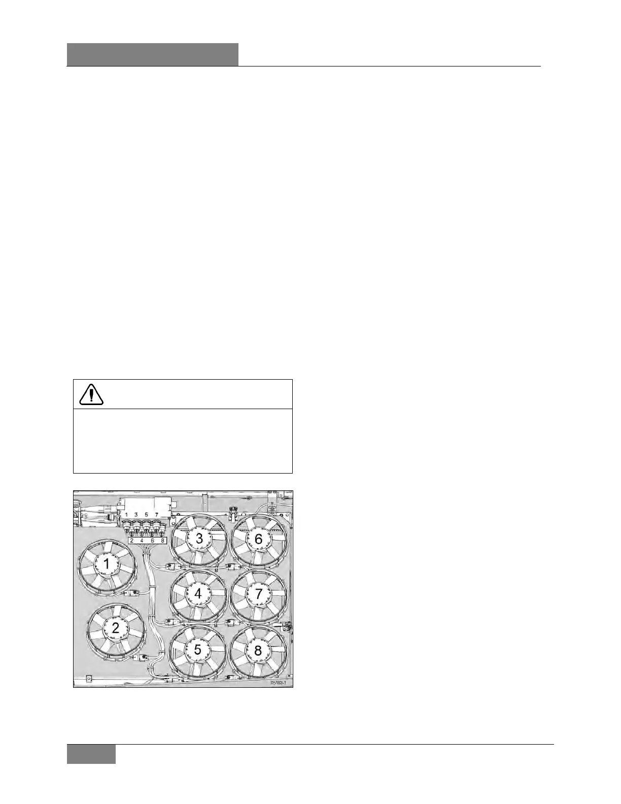
The cooling assembly uses a total of 8 identical
12 inches (305mm) brushless (24V) electric
cooling fans to dissipate the heat generated by
the engine. The first two fans are used by the
charge air cooler (CAC) to cool the hot
compressed air coming from the turbocharger;
the remaining 6 fans are used by the radiator
(Figure 22 & Figure 23).
Each fan is fixed to a shroud by 4 hex screws
and is individually connected to the circuit
breaker box through a main wiring harness (refer
to section 06 ELECTRICAL for more information
regarding breaker box components and
harness).
The shroud assists in directing the air flow
generated by the fans through the radiator/CAC
assembly with maximum efficiency and is sealed
to the radiator/CAC assembly (cooling pack) with
rubber seals. The shroud is hinged and can be
“pivoted” out of the way to inspect or clean the
radiator/CAC fins and tanks.
CAUTION
The fan shroud is an essential component
used to achieve maximum air flow capacity
through the cooling assembly. To prevent
overheating, inspect rubber seal regularly to
ensure proper sealing.
FIGURE 22: FAN ORDER AND CONNECTOR NUMBER
AT CIRCUIT BREAKER BOX
 Loading...


