SECTION 22: HEATING AND AIR CONDITIONING
DOB 1300-1556 | X3-45 Commuter PA-1648 Maintenance Manual First release Oct 2020
5. HVAC SYSTEM TESTING AND
TROUBLESHOOTING
Before undertaking any troubleshooting on the
HVAC system, study the appropriate wiring
diagrams to get a complete understanding of the
HVAC components circuitry, read and
understand section 06: ELECTRICAL of this
manual under "Troubleshooting And Testing The
Multiplex Vehicles" and "Test Mode For
Switches And Sensors". The information
included in these paragraphs is necessary for
troubleshooting the HVAC system on Multiplex
vehicles.
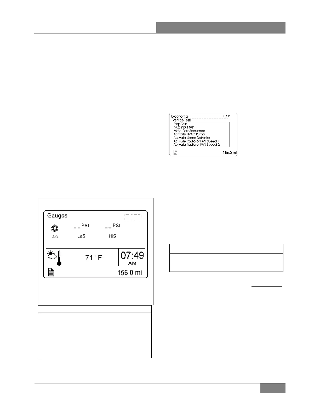
5.1 ON DEMAND DISPLAY OF A/C
SYSTEM HIGH AND LOW SIDE
PRESSURE
Refrigerant pressures can be displayed in the
Driver Information Display (DID) by selecting
“Gauges” menu and pressing the down arrow to
the fifth displayed screen.
A/C Compressor Pressure
Displays the A/C system’s
value (LoS=low side) and discharge pressure
value (HiS=high side).
When starting the A/C compressor, allow
enough time before checking pressures in
order to give the system a chance to build its
pressure
.
During the first 3 seconds after
startup, the compressor is active on 4
cylinders and the A/C valve is open regardless
of the pressure readings.
5.2 ON DEMAND ACTIVATION OF HOT
WATER CIRCULATING PUMP
In Diagnostics/Vehicle Test mode on the DID,
the heating system circulating pump can be
turned on manually by selecting ACTIVATE
HVAC PUMP command. This feature allows
verification of the circulating pump when inside a
garage. This is also useful when working on the
heating system to remove air pockets trapped in
the system.
In normal operation, the heating system
circulating pump operates only when the
ambient temperature is 50°F or lower.
5.3 TEMPERATURE SENSORS
The following table can be used for
troubleshooting the following temperature
sensors:
1) Driver area temperature sensor (SE21);
2) Passenger area temperature sensor (SE25);
3) Outside air temperature sensor (SE20).
NOTE
The driver’s area air temperature sensor is
located below the dashboard, just
ahead of
the driver's right knee.
The table values are for unloaded, disconnected
temperature sensors (thermistor) probed at the
temperature sensor connector pins.
If the temperature sensor resistance value is
measured at the multiplex module inputs, the
measured value includes a parallel 33 kiloohm
resistor.
 Loading...


