Mi14-01E Page 34 / 38 Rev: Oct 2021
3.2 FIRST LIFT
A first lift of the bus is necessary. This first lift will allow tow cans or blocks to be placed underneath the
drive axle tires.
1. Prepare the bus
for towing as instructed in
paragraphs 2.1 and 2.1.1
2. If not already done, chock the front wheels.
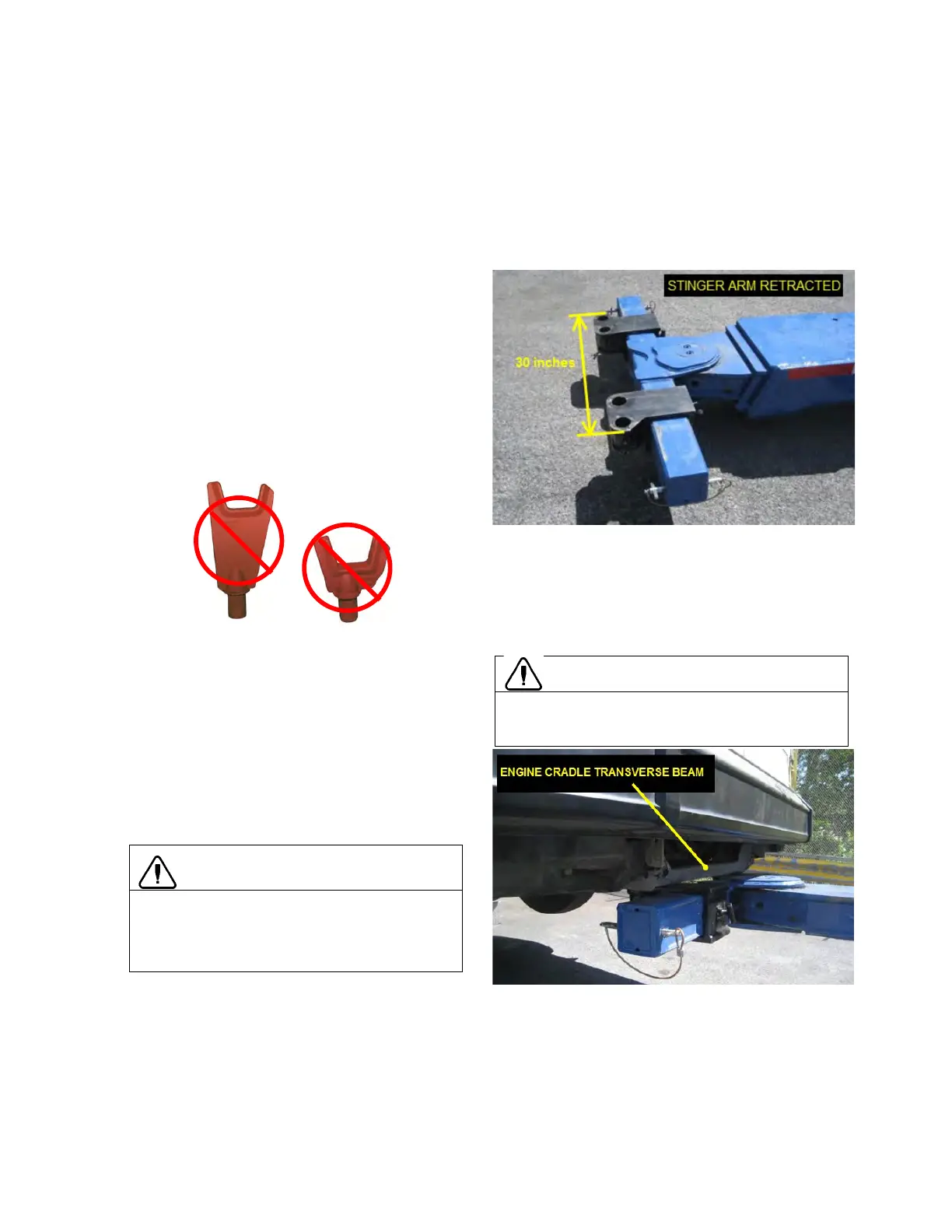
3. Retract the tow truck stinger arm (Figure 62).
4. Pre-
adjust spacing between the axle fork
holders. The spacing between the most distant
edges of the folk holders should be 30 inches
(
Figure 62).
No axle forks will be used for this first lift
TALL REGULAR
Figure 62
5. Deploy the tow truck stinger arm. Place the fork
holders under the engine cradle transverse
beam as shown on Figure 63. Lift the tow bar
until the fork holders come into contact with the
cradle transverse beam.
Lifting from the engine cradle is the least
preferred option and should be done only if
lifting from under the side-members shown
on figure 53 cannot be achieved
CAUTION
Remember, lifting the rear end from the side-
members located under the engine cradle or
by the engine cradle itself may cause
structural damage.
Use caution when lifting from the engine cradle
transverse beam. M
aintain the bus in that
situation during the shortest period of time.
Figure 63
 Loading...


