SECTION 12: BRAKE AND AIR SYSTEM
DOB 1300-1556 | X3-45 Commuter PA-1648 Maintenance Manual Section 12 revised Jan 2021
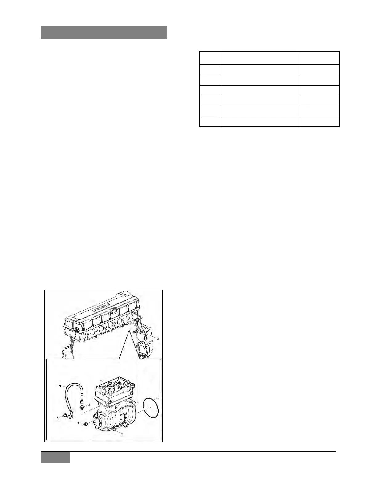
11. AIR COMPRESSOR
The Wabco System Saver 636 Twin Cylinder air
compressor is located on the right side of the
engine, at the flywheel end (Figure 18). Its
function is to provide and maintain air under
pressure to operate devices in brake and air
systems.
The compressor is driven by the ring gear, and
is water cooled. Engine coolant is fed to the
compressor through a flexible hose tapped into
the block water jacket and connected to the rear
of the compressor. Coolant returns from the top
of the compressor (governor side) through a
flexible hose to the engine pump.
The air is taken from the air intake manifold and
entered in the top of the compressor. The
compressed air is pushed into the discharge line
located on side of the compressor, which sends
air to the air dryer. Lubricating oil is supplied to
the compressor by a line from the cylinder block
oil gallery connected to the air compressor.
Lubricating oil returns to the engine crankcase
through the air compressor drive assembly.
Maintenance and repair information on the
Wabco 636 Twin Cylinder air compressor is
supplied in the applicable booklet, found on your
Technical Publications USB flash drive.
FIGURE 18: AIR COMPRESSOR LOCAT ION
Item Description Notes
1 Air Compressor Wabco 636
2 O-ring
3 Stud (3) M12
4 Flange Nut (3)
5 Nipple (2)
6 Hose Assembly
11.1 COMPRESSOR REMOVAL AND
INSTALLATION
1. Exhaust compressed air from air system by
opening the drain valve of each air tank.
2. Drain the engine cooling system. See
Section 5: "Cooling System".
3. Access the compressor by the engine R.H.
side compartment. Identify and disconnect
all air, coolant and oil lines from the
compressor assembly.
4. Remove the three compressor flange
mounting nuts.
5. Slide air compressor rearward to disengage
the hub from coupling. Remove the air
compressor.
6. Remove and retain the oil supply tube that
runs between the compressor and the
engine.
7. Reverse removal procedure for installation.
 Loading...


