SECTION 22: HEATING AND AIR CONDITIONING
DOB 1300-1556 | X3-45 Commuter PA-1648 Maintenance Manual First release Oct 2020
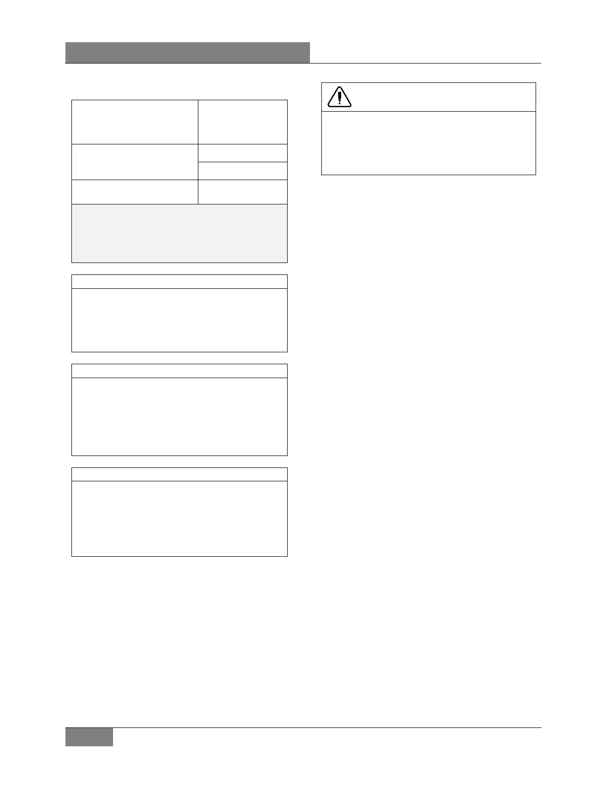
Example of readings taken:
compressor suction
converted to temperature
with chart
40°F
Temperature on remote bulb
Low swing 44°F
High swing 54°F
swing
49°F
Formula for superheat
T° at bulb – T° suction = T° superheat
49°F ‒ 40°F = 9°F
The low swing of the superheat should be a
minimum of 4°F (2,2°C) higher at the remote
bulb and have an average of 12 to 16°F (4 to
6°C) higher range at the bulb than the fitting at
the expansion valve.
The thermal expansi
on valve has a MOP
(maximum operating pressure) of 55 psi. At
this setting, the valve is completely open.
If the temperature at the bulb is greater than
50°F, do not try to adjust superheat as the
valve is almost completely opened.
To reduce the superheat, increase refrigerant
flow
by turning adjusting screw
counterclockwise on expansion valve
. To
increase superheat, flow of refrigerant is
reduced by turning adjustment screw of
clockwise.
7. Regulate suction pressure to temperature
reading according to the temperature chart
or to the R-134a temperature scale on the
pressure gage.
Example: Suction pressure 30 psi (207 kPa)
converted to 32
o
F (0
o
C) on the chart. If
temperature reading is 40
o
F (4,4
o
C), subtract
32
o
F (0
o
C) and the result will be 8
o
F (4,4
o
C) of
superheat.
CAUTION
Before proceeding with the expansion valve
adjustment, check for restriction on suction
side for plugged filter dryer and partially open
valves. These conditions will give a high
superheat.
4.9.3 Maintenance
1. Pump down the system as previously
indicated in this section.
2. Disconnect the external equalizer line from
the underside of the power head, and
unclamp the remote control bulb from the
evaporator coil outlet line.
3. Remove the two cap screws holding the
power assembly to the valve body flange.
Lift off the power assembly and remove the
cage assembly.
4. When reassembling, replace with the new
gaskets in proper location. Make sure the
two lugs on the cage assembly fit into
grooves provided in the power assembly.
Do not force the valves together. The cage
must fit properly before tightening the body
flange. Tighten bolts evenly.
5. Check for leaks.
Safety Instructions
1. Make sure the valve is installed with the
flow arrow on the valve body corresponding
to the flow direction through the piping
system.
2. Before opening any system, make sure the
pressure in the system is brought to and
remains at the atmospheric pressure.
Failure to comply may result in system
damage and/or personal injury.
4.9.4 Driver’s Unit
The function and operation of the driver's unit
expansion valve are similar to the central
system, but no superheat adjustment is required
(
FIGURE 33).
 Loading...


