DOB 1300-1556 | X3-45 Commuter PA-1648 Maintenance Manual Section 06 revised release October 2021
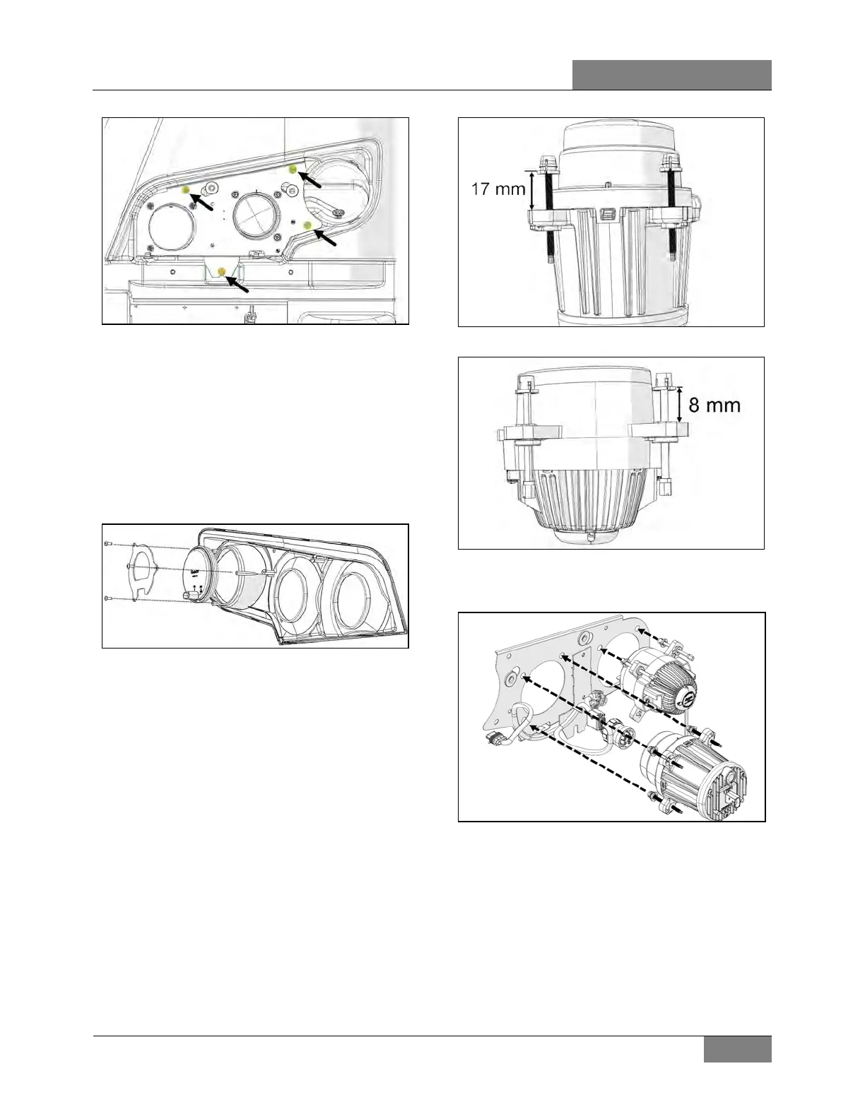
FIGURE 61: 4 SCREWS HOLDING THE HEADLIGHT
MODULE
5. Unplug the connectors.
15.2.1 Directional Turn Signal Replacement
The front turn signal is part of the front bezel.
The turn signal is a sealed module and should
be replaced as an assembly.
1. Unscrew 3 fasteners and replace the turn
signal module.
FIGURE 62: UNSCREW 3 FASTENERS
15.2.2 Low & High Beam LED module
Replacement
1. Remove the existing LED module complete
with adjuster screw.
2. Before installing the LED module, make sure
the adjuster screw is adjusted according to
the dimension on the two following images.
FIGURE 63: LOW BEAN LED MODULE
FIGURE 64: HIGH BEAN LED MODULE
3. Install the LED module. Snap the adjuster
screw ends through the plate.
FIGURE 65: SECURING THE LED MODULE
15.3 HEADLAMP AIM ADJUSTMENT
Horizontal and vertical aiming of headlamp
module is provided by adjusting screws that
pivot the module in the housing for the proper
alignment.
1. Headlamp aiming and inspection can be
accomplished by visual means. This is done
on a screen located at a distance of 25 feet
(7,6 m) of the headlamps. It should be of
 Loading...


