DOB 1300-1556 | X3-45 Commuter PA-1648 Maintenance Manual Section 06 revised release October 2021
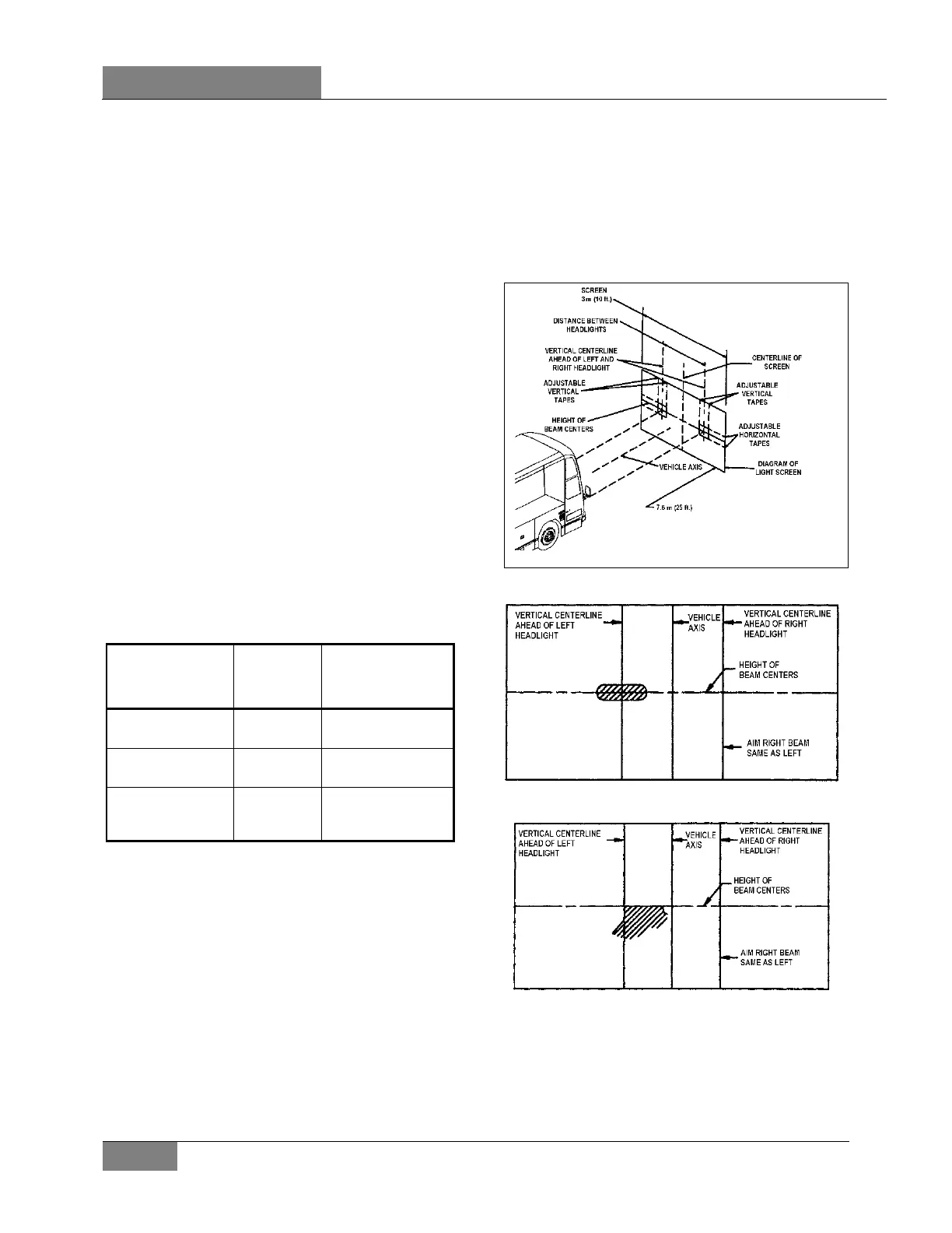
adequate size with a matte-white surface
well shaded from extraneous light and
properly adjusted to the floor area on which
the vehicle stands. Provisions should be
made for moving the screen or its vertical
centerline so that it can be aligned with the
vehicle axis. In addition to the vertical
centerline, the screen should be provided
with four laterally adjustable vertical tapes
and two vertically adjustable horizontal
tapes.
2. The four movable vertical tapes should be
located on the screen at the left and right
limits called for in the specification with
reference to centerlines ahead of each
headlamps assembly.
The headlamp centerlines shall be spaced either
side of the fixed centerline on the screen by ½
the lateral distance between the light source
centers of the pertinent headlamps. The
horizontal tapes should be located on the screen
at the upper and lower limits called for in the
specification with reference to the height of
beam centers and the plane on which the
vehicle rests, not the floor on which the screen
rests.
TABLE 1 – VERTICAL BEAM AIM GUIDELINES
Headlamp
(centerline)
Mounting Height
Nominal
Vertical
Aim
Aim Inspection
Limits for Vertical
Aim
56 to 90 cm (22 to
36 inch)
0 Vertical 10 cm (4 inch) up to
10 cm ( 4 inch) down
90 to 120 cm (36 to
48 inch)
5 cm (2 inch)
down
5 cm (2 inch) up to 15
cm (6 inch) down
120 to 140 cm (48 to
54 inch)
10 cm (4
inch) down
4 cm (1.5 inch) up to
16.5 cm (6.5 inch)
down
3. The nominal vertical aim position on lower
beam headlamps shall be adjusted based
on the headlamp mounting height, from the
ground to the light source center of the
headlamp, according to table1.
4. High beam headlamps are aimed so that the
center of the high-intensity zone is located at
the horizontal and straight ahead vertically
(Figure 67).
5. Low beam headlamps are aimed so that the
top edge (the cutoff) of the high-intensity
zone is at the vertical location as per Table 1
and the left edge of the high-intensity zone
is at the vertical centerline of the headlamp
(Figure 68).
6. The inspection limits for high-beam
headlamps shall be with the center of the
high-intensity zone from 10 cm (4 in) up to
10 cm (4 in) down; and, from 10 cm (4 in)
left to 10 cm (4 in) right on a screen at 7.6 m
(25 ft) (Figure 69).
FIGURE 66: ALIGNMENT OF HEADLAMP AIMING
SCREEN
FIGURE 67: UPPER BEAM HIGH-INTENSITY ZONE
PROPER LOCATION ON SCREEN
06503
FIGURE 68: LOWER BEAM HIGH-INTENSITY ZONE
PROPER LOCATION ON SCREEN
 Loading...


