DOB 1300-1556| X3-45 Commuter PA-1648 Maintenance Manual Section 23 revised Nov 2021
2. HUB ODOMETER
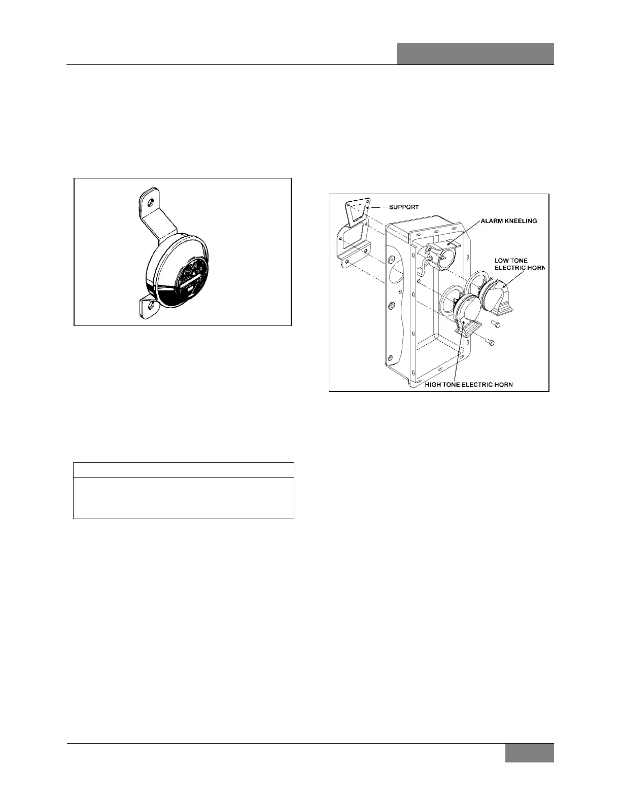
A wheel hub odometer (Figure 1) have been
installed on the R.H. side of the drive axle. It
indicates the total distance in miles covered by
the coach since it has left the factory, including
road testing.
FIGURE 1: HUB ODOMETER 23024
2.1 OPERATION
The hub odometer is calibrated for a specific
wheel size (diameter). Wheel rotation causes a
mechanism inside the hub odometer to record
distance after a predetermined number of
rotations. The unit should be serviced at a
competent speedometer repair facility.
Do not use paint, solvent or thinner on hub
odometer face or on plastic hubcaps. Do not
weld on hub odometer.
2.2 REMOVAL
To remove the unit, remove the two lock nuts
and washers securing it to the wheel hub, and
pull the unit off the studs.
2.3 INSTALLATION
Place the hub odometer unit over the wheel hub
studs. Replace the lock washers and nuts.
Torque stud nuts.
TORQUE: 110-165 lb-ft (149-224 Nm)
3. HORN INSTALLATION
The electric and air horns are located in a plastic
box under the front step well and are accessible
from the front body substructure. Refer to
Operator’s or Owner’s Manual for operation.
FIGURE 2: ELECTRIC & AIR HORN INSTALLATION 23420
3.1 ELECTRIC HORN MAINTENANCE
When needed, the electric or air horn can be
serviced or replaced using the following
procedure:
1. Raise vehicle by the jacking points;
2. Unplug the cable connector;
3. Disconnect the air tube if applicable;
4. Loosen the retaining bolts;
5. Service or replace the defective horn;
6. Reinstall by reversing procedure.
 Loading...


