SECTION 10: FRONT I-BEAM AXLE
D DOB 1300-1556 | X3-45 Commuter PA-1648 Maintenance Manual First release Oct 2020
with the wheels in the normal ‘’straight-ahead’’
position of the steering gear.
Incorrect toe-in results in excessive tire wear
caused by side slippage and also steering
instability with a tendency to wander. Toe-in may
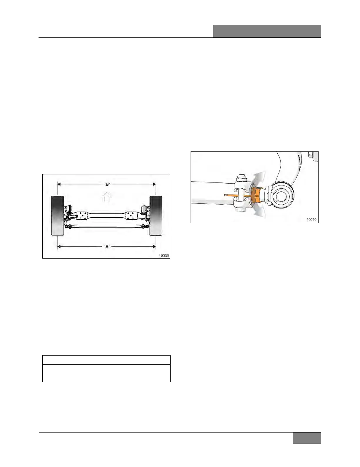
be measured from the center of tire tread or from
the inside of the tires. Take measurements at both
front and rear of axle (see ’’A” and ‘’B’’ in Figure
6).
When setting toe-in adjustment, the front
suspension must be neutralized; that is, all
component parts must be in the same relative
position when marking the adjustment as they
will be when in operation.
To neutralize the suspension, the vehicle must
be rolled forward, approximately ten feet.
FIGURE 6: TOE-IN MEASUREMENT
For toe-in specifications, refer to paragraph 8
‘’Alignment specifications’’ in this section.
By rolling the vehicle forward, all tolerances in
the front suspension are taken up and the
suspension is then in its normal operating
position. Neutralizing the front suspension is
extremely important, especially if the vehicle has
been jacked up in order to mark the tires.
Otherwise, the front wheels will not return to their
normal operating position due to the tires
gripping the floor surface when the vehicle jack
is lowered.
‘’Toe-in’’ measurements must be taken at the
horizontal axis of the wheel centerline.
7.8.1 Inspection and Adjustment
Before adjusting front wheel toe-in, first check
the camber angles and make the necessary
corrections.
1. Measure the toe-in.
2. If the toe-in measurement is not within the
specified tolerance, carry out the following
procedure :
a. Loosen the pinch bolt on the right hand
(curb side) tie rod end where the
adjuster sleeve is located.
b. Turn the adjuster sleeve (Figure 7) until
the specified toe-in measurement is
obtained.
c. Tighten the clamp bolt nuts
TORQUE: 118-133 lb-ft (160-180 Nm)
FIGURE 7: FINE ADJUSTER SLEEVE ON TIE ROD
 Loading...


