DOB 1300-1556 | X3-45 Commuter PA-1648 Maintenance Manual First release Oct 2020
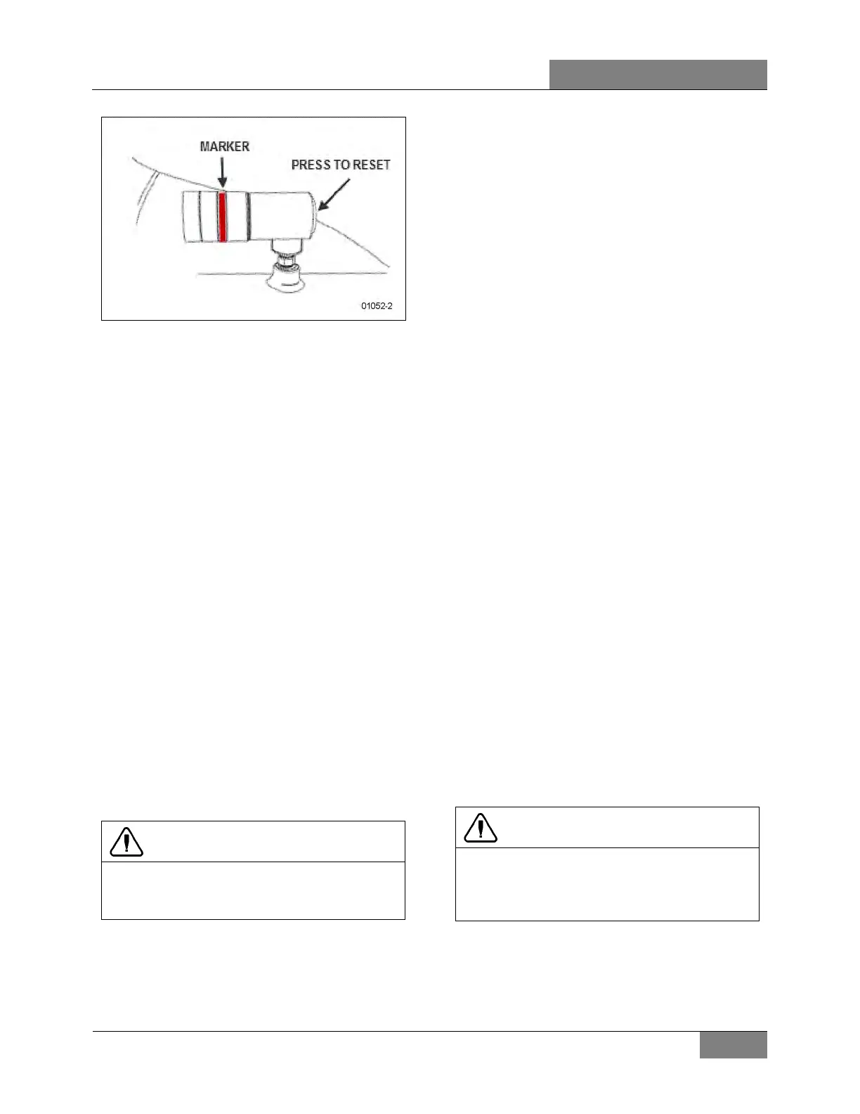
FIGURE 27: RESTRICTION INDICATOR
5.2 GENERAL RECOMMENDATIONS
The following maintenance procedures will
ensure efficient air cleaner operation:
1. Keep the air cleaner housing tight on the air
intake pipe;
2. Make sure the correct filters are used for
replacement;
3. Keep the air cleaner properly assembled so
the joints are air-tight;
4. Immediately repair any damage to the air
cleaner or related parts;
5. Inspect, clean or replace the air cleaner or
elements as operating conditions warrant.
Whenever an element has been removed
from the air cleaner housing the inside
surface of the housing must be cleaned with
a soft clean cloth;
6. Periodically inspect the entire system.
Dust-laden air can pass through an almost
invisible crack or opening which may
eventually cause damage to an engine;
7. Never operate the engine without an element
in the air cleaner assembly;
CAUTION
Do not ignore the Warning given by the air
restriction indicator. This could result in
serious engine damage.
8. Store new elements in a closed area free
from dust and possible damage.
6. ACCELERATOR PEDAL
The EFPA (Electronic Foot Pedal Assembly)
connects the accelerator pedal to a
potentiometer (a device that sends an electrical
signal to the ECM, which varies in voltage,
depending on how far down the pedal is
depressed). The EFPA is installed in the space
normally occupied by a mechanical foot pedal. It
has maximum and minimum stops that are built
into the unit during manufacturing.
6.1 PEDAL ADJUSTMENT
The EFPA contains a throttle position sensor
that varies the electrical signal sent to the ECM.
The sensor must be adjusted whenever an
EFPA is serviced. In addition, the sensor should
be adjusted any time codes 21 and 22 are
flashed.
With the ignition "ON" and the proper diagnostic
tool (DDR) (for information regarding the DDR,
see "01 ENGINE" in this manual), check the
throttle counts at idle and full throttle positions.
Proper pedal output should be 20/30 counts at
idle and 200/235 at full throttle. If adjustment is
necessary, remove the potentiometer retaining
screws and rotate the potentiometer clockwise to
increase counts or counterclockwise to
decrease. When correct output is confirmed,
tighten retaining screws.
6.2 POTENTIOMETER REPLACEMENT
1. Disconnect cable harness connector.
2. Loosen the two screws and remove
potentiometer. Retain for re-assembly.
3. Discard potentiometer (Figure 28).
CAUTION
Note the routing and clamping locations of the
cable before disassembly. Proper cable
routing and fastening is critical to the
operation of this system.
4. Position new potentiometer. Press
potentiometer onto the potentiometer shaft,
matching cutouts in shaft to drive tangs of
potentiometer. Apply hand pressure until
 Loading...


