DOB 1300-1556 | X3-45 Commuter PA-1648 Maintenance Manual First release Oct 2020
FIGURE 16: I-BEAM FRONT AXLE PIT MAN ARM
ADJUSTMENT
6. Add reference marks to the arm and shaft if
necessary to ensure correct alignment at
reassembly.
7. Use a suitable puller and remove pitman
arm.
11.2 INSTALLATION
1. Position pitman arm on sector gear shaft
with reference marks aligned.
2. Install fixing nut.
TORQUE: 470-570 lb-ft (637-773 Nm)
Use a new nut if the previously removed nut
was punched.
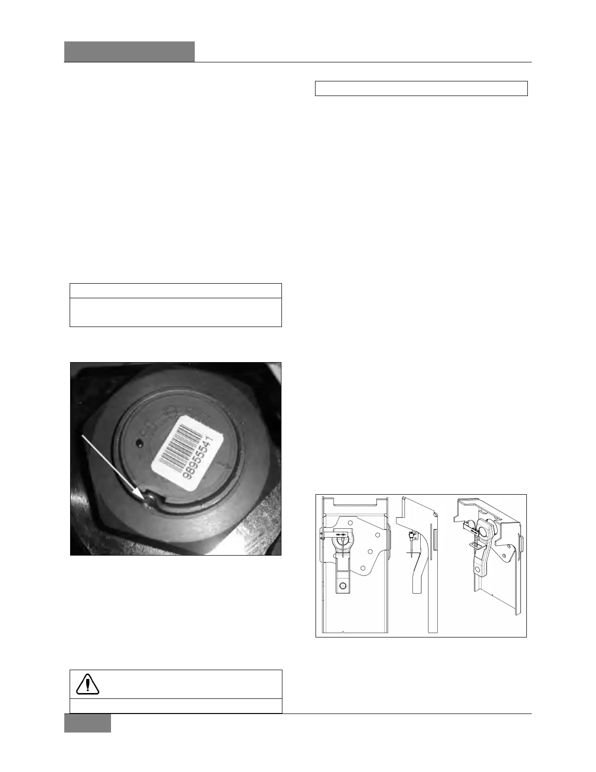
1. Lock nut with sector shaft using a punch
mark into the groove (Refer to Figure 17).
FIGURE 17: FIXING NUT PUNCH MARK 16098
2. Connect drag link to pitman arm while
ensuring that rubber stabilizer is in
place on the rod end. Install washers.
Tighten nut and install a new cotter pin.
Depending on axle type, select the
appropriate torque,
TORQUE: 165-236 lb-ft (224-320 Nm)
CAUTION
Input shaft marks must be aligned before
11.3 ADJUSTMENT
1. Disconnect the drag link from pitman arm.
Center steering wheel by dividing the total
number of steering wheel turns in two.
Scribe a reference mark on steering gearbox
at the center previously determined.
2. Using a protractor, check the angle of the
pitman arm (refer to Figure 16 for details).
3. The pitman arm should be adjusted with
reference marks aligned or to an angle of
2.5º towards front of vehicle (I-Beam axle) in
relation with the vertical axis. If not, unscrew
and remove fixing nut. Remove the pitman
arm according to the procedure outlined
under previous heading "Pitman arm
removal". Adjust to the proper angle.
4. When adjustment is achieved, replace fixing
nut and tighten
TORQUE: 470-570 lb-ft (637-773 Nm)
11.4 TAG AXLE UNLOAD - SWITCH
ADJUSTMENT
1. Make sure vehicle wheels are straight and
facing forward.
2. Line up switch lever with reference to the
bracket center (Refer to Figure 18).
FIGURE 18: TAG AXLE UNLOADING SWITCH
ADJUSTMENT
14061
 Loading...


