SECTION 22: HEATING AND AIR CONDITIONING
DOB 1300-1556 | X3-45 Commuter PA-1648 Maintenance Manual First release Oct 2020
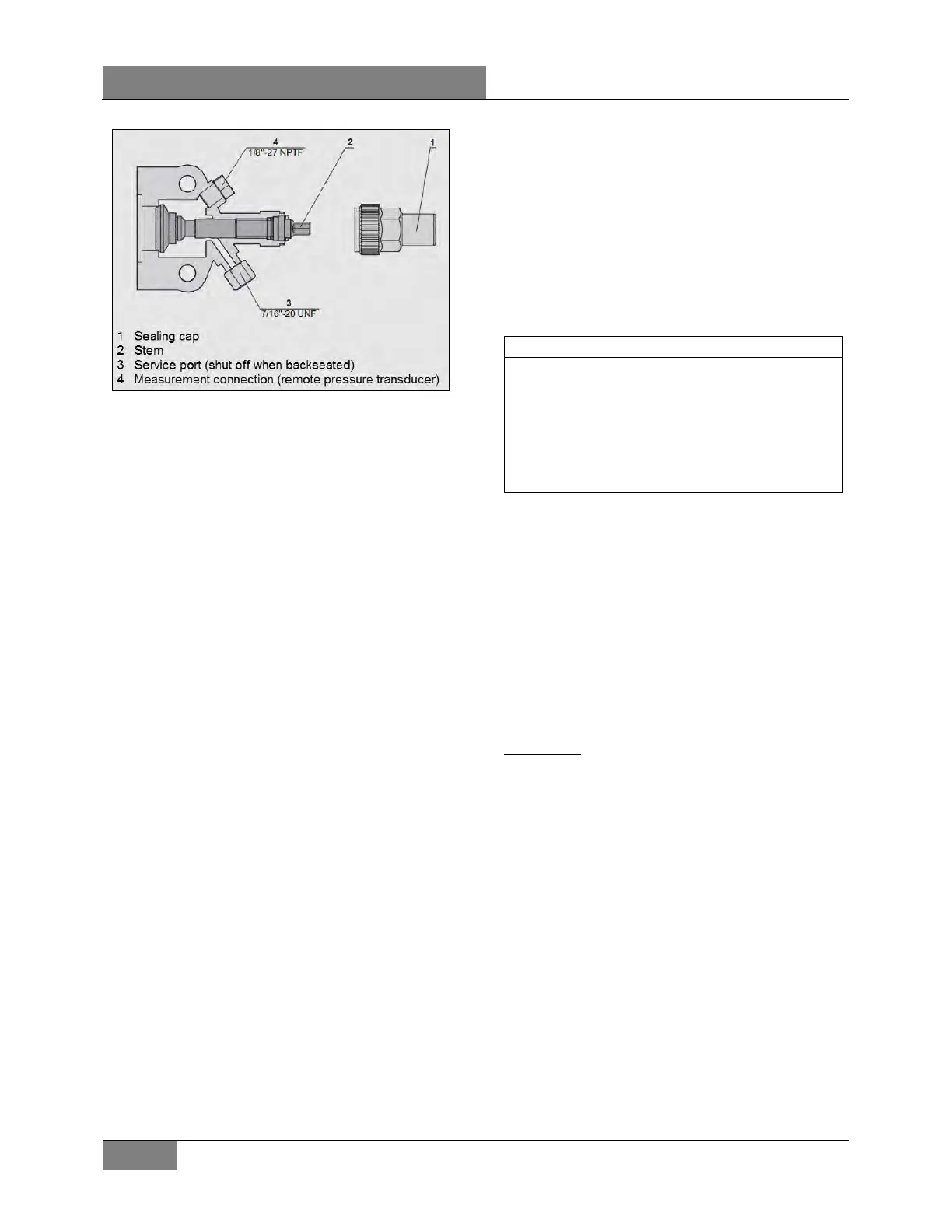
FIGURE 57: COMPRESSOR SHUTOFF VALVE IN FRONT
SEATED POSITION
2. Run the system for 10 minutes and then
shut it off.
3. Close (front seat) the receiver tank outlet
shutoff valve by turning the stem clockwise
(Figure 57).
MAX TORQUE: 21 lb-ft (28 Nm)
4. Backseat the compressor suction shutoff
valve (FIGURE 56).
MAX TORQUE: 12 lb-ft (16 Nm)
5. Install an appropriate pressure gage set on
the service port and then turn the shutoff
valve forward ¼ turn more or less until a
visual check of the suction pressure is
possible.
6. Disconnect the low pressure transducer.
The multiplex system will establish a default
value of 34 psig and this will allow pulling
down the A/C compressor to 0 psig. Note:
the low-pressure transducer must be
reconnected after the pumping down
operation is complete.
7. Run the A/C compressor until suction
pressure is pulled down to 0 psig.
8. Disconnect the compressor clutch to stop
the compressor from pulling the system into
a vacuum. Vacuum is not required. The
pressure will probably slowly increase on the
suction side. When it reaches 10 psig,
reconnect the clutch and repeat the pull
down to pull down this residual pressure.
This process might need to be repeated a
couple of times until the suction pressure
drops and remains to 0 psig.
9. Stop the compressor.
10. Close (front seat) the suction shutoff valve
on the compressor (Figure 57).
MAX TORQUE: 21 lb-ft (28 Nm)
11. At this point, C24 can be disconnected to
isolate the section of the system located
between the receiver tank outlet shutoff
valve and the passengers’ unit liquid
solenoid valve. Doing so would be useful to
perform replacement of the filter dryer, for
example.
During this operation, care must be taken not
to fill the receiver tank over the upper sight
glass. If so, stop process immediately. Always
allow refrigerant piping and units to warm up
to the ambient air temperature before opening
system or sweating will take place inside the
lines.
6.7.5 Adding Vapor State Refrigerant
Addition of vapor state refrigerant is carried out
to compensate for hose permeation and shaft
seal losses over a long period and is done from
the suction side while compressor is in
operation.
A typical sign of refrigerant low charge would be
A/C lower performance experienced by the user.
Perform the usual leak inspection and correct
any leaks before adding refrigerant.
Verification
Perform the following verification:
1- A vehicle stopped for more than 4 hours
should show the lower receiver tank sight
glass full at room temperature or with some
level if ambient temperature is high. This
method is less accurate when ambient
temperature gets high.
2- With the AC on for at least 10 minutes, the
moisture indicator sight glass (FIGURE 58)
should be clear, not milky, without bubbles
in the stream of refrigerant. Bubbles in the
moisture indicator sight glass are sign of
refrigerant low charge. The filter-dryer
nearby should be near constant
temperature, less than 5°F differential
between inlet and outlet. A partially blocked
filter will make some flash gas and give a
“milky” sight glass.
 Loading...


