DOB 1300-1556 | X3-45 Commuter PA-1648 Maintenance Manual Section 06 revised release October 2021
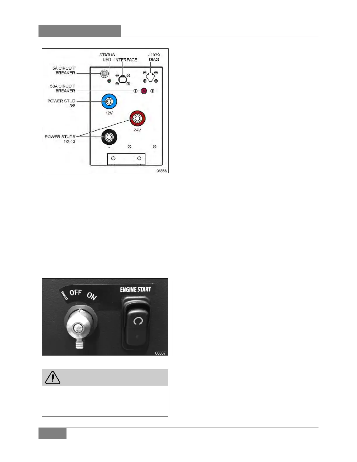
FIGURE 48: STARTING MODULE
This module houses supercapacitors that derive
power from the vehicle electrical system and
discharges it when starting the engine.
On engine start-up, the module provides power
in parallel with the standard batteries. If the
standard batteries are depleted, the module will
provide enough power for engine start-up.
A vehicle equipped with a starting module will
have a differing starting switch arrangement on
the dashboard. This system uses an on/off
ignition switch and an engine starting (cranking)
switch.
FIGURE 49: SWITCH ARRANGEMENT WITH STARTING
MODULE
11.1 STARTING THE VEHICLE WITH
DEPLETED BATTERIES.
With a supercapacitor starting module, if the
batteries are depleted and the charging system
works correctly, it is still possible to start the
vehicle.
Place ignition switch to the “ON” position (Figure
49)
Press and hold engine start switch (Figure 49)
until engine is running and keep holding
minimum of 3 seconds after engine run.
Holding the switch provides the circuit with
power coming from the starting module.
11.2 STARTING MODULE STATUS LED
The bi-color (red/green) LED is an indicator for
how the starting module is functioning. The
green side of the LED is connected parallel with
the contactor. The red side is connected to an
output on the module's programmable logic
controller (PLC).
Green: Anytime the LED Status Indicator is
illuminated green, the contactor is closed. In a
typical engine-starting event you will see the
LED illuminate during engine cranking and then
go out for several seconds after the engine has
started. The LED will then illuminate again and
could remain illuminated for several seconds
based on the condition of the module. The LED
may “cycle” depending on the vehicle or system
voltage during the recharging events.
Red: The PLC monitors the capacitor voltage
during and after the recharge cycle. If the
capacitor voltage drops to below an acceptable
level in the first 5 minutes after the recharge, the
red LED will flash, indicating a fault.
If at any time while the PLC is powered up, the
5A circuit breaker trips or the capacitor voltage
level drops below 4 volts the red LED will flash.
(Source: KBI)
11.3 TROUBLESHOOTING
Refer to supplier manual KSM Starting Module
Manual RevD.pdf from KBI on the technical
publications web site or on the technical
publications USB drive for troubleshooting
instructions.
WARNING
The starting module is a polarity sensitive
device. Polarity should be strictly observed
when connecting the KAP
any circuit
 Loading...


