SECTION 12: BRAKE AND AIR SYSTEM
DOB 1300-1556 | X3-45 Commuter PA-1648 Maintenance Manual Section 12 revised Jan 2021
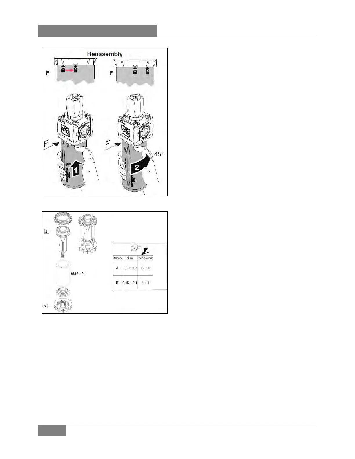
FIGURE 11: ACCESSORY AIR FILTER BOWL
INST ALLAT ION
FIGURE 12: ACCESSORY AIR FILTER ARRANGEMENT
7. AIR GAUGES (PRIMARY, SECONDARY
AND ACCESSORY)
The air pressure gauges, located on the
dashboard (see "Operator's Manual" or
“Owner’s Manual”), are fed from pressure
transducer installed on the DC-4 double check
valve, located on the pneumatic accessories
panel in the front service compartment.
The latter is connected to the lines running from
the primary and secondary air tanks, as shown
on the pneumatic system diagram provided with
the vehicle. The accessory air gauge is
connected to the front pneumatic panel in the
front compartment of the vehicle. The vehicle
should never be set in motion until the buzzer
alarm and warning lights turn off, i.e. when air
pressure registers at least 85 psi (414 kPa).
Moreover, if pressure drops below 85 psi
(414 kPa), the "Low air pressure" warning lights
will turn on, and the "Low air pressure" buzzer
will sound. Stop the vehicle immediately,
determine and correct the cause(s) of pressure
loss. Check the gauges regularly with an
accurate test gauge. Replace the gauge with a
new unit if there is a difference of 4 psi (27 kPa)
or more in the reading.
8. AIR DRYER
 Loading...


