DOB 1300-1556 | X3-45 Commuter PA-1648 Maintenance Manual First release Oct 2020
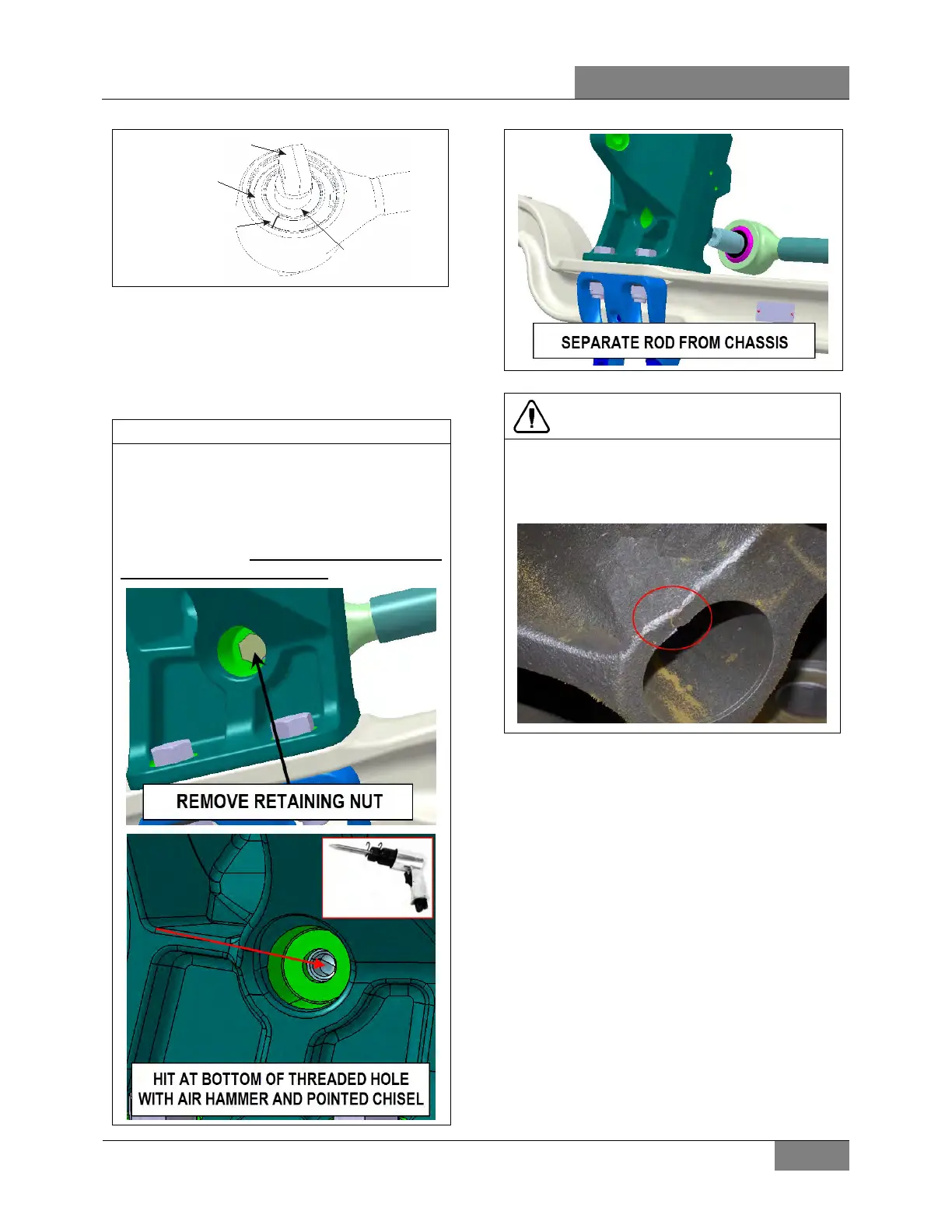
Ball pin
External joint shell
Radial cracking of the
sheet-metal race
Par
tial separation
is permitted
FIGURE 7: BALL PIN BUSHING
3.3.2 Radius Rod Removal
1. Unscrew the nuts (or bolts) at each extremity
of the radius rod.
2. Remove the radius rod.
One end of the transversal radius rod is fitted
with a conical (taper) pin that will require the
use of an air hammer and a pointed 13mm
(1/2inch) diameter chisel to remove it from the
chassis (after the retaining nut is removed
from the rod end). Care must be taken not to
damage the rod pin threads.
CAUTION
Do not hit the cast parts
disengage taper radius rods; this could lead to
cracking and/or deformations of the cast
parts.
3.3.3 Stripping Down
Strip down the defective joint by removing the
Circlip, and ball pin/bushing assembly.
Clean out housing bore and Circlip groove.
3.3.4 Radius Rod Assembly
The assembly work may be done only by a
recognized specialized workshop. Ensure that
old and new parts do not get mixed up with each
other. For this reason, all the old parts are to be
scrapped immediately after a joint has been
stripped down.
A complete repair set must be used for each
joint repaired, i.e. use of only part of a repair set
is not permissible.
Execute assembly of the new joint parts in the
following sequence:
 Loading...


