DOB 1300-1556 | X3-45 Commuter PA-1648 Maintenance Manual First release Oct 2020
1. Complete lubrication of the contact surface
between housing bore and ball pin elastomer
through application of grease.
Apply the supplied grease, only if you are
using a repair kit.
2. Insert ball pin/bushing, assembly. Ensure
that the bolt bores are in the correct position
in relation to the axis of the tube.
3. Place joint in receiving fixture and mount
annular assembly tool on the housing. Then
locate Circlip in the housing using axial load
with the aid of the assembly matrix.
4. Opening of the Circlip is located at 45° to the
housing shaft axis. Make sure that the
Circlip is perfectly engaged in the housing.
3.3.5 Radius Rod Installation
1. Snug up the nuts (or bolts) and repeat at the
other end.
2. Refer to heading "Suspension Height
Adjustment" later in this section, and set the
vehicle to normal ride height.
3. With the vehicle at normal ride height,
tighten all radius rod anchor studs nuts or
bolts to specification.
RADIUS ROD NUT/BOLT
TORQUE: 225-255 lb-ft (305-346 Nm)
RADIUS ROD STUD
TORQUE: 90-110 lb-ft (122-149 Nm)
TRANSVERSAL RADIUS ROD (CONICAL)
TORQUE: 185-227 lb-ft (251-308 Nm)
CAUTION
It is extremely important upon reconnection of
the rods that the proper clearance height
between the axle and body be maintained.
Otherwise, the rubber bushings in radius rod
ends will become preloaded, thus reducing
their life span.
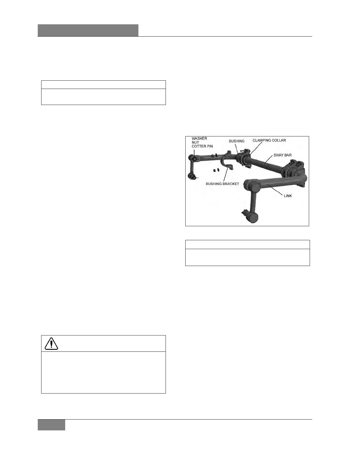
3.4 SWAY BAR
A sway bar is connected to the front axle to
increase vehicle stability. It controls lateral
motion (swaying movement) of the vehicle
(Figure 8).
3.4.1 Removal
1. Disconnect the two links from sway bar.
2. Safely support the sway bar. Unbolt the four
bushing brackets from subframe.
3. Remove sway bar.
FIGURE 8: SWAY BAR 16028
Sway bar bushings are slit to ease their
removal.
3.4.2 Installation
1. Loosely install the sway bar.
2. Tighten the eight bushing brackets nuts
according specifications.
TORQUE: 80-100 lb-ft (108-136 Nm)
3. Tighten sway bar link upper nuts and lower
nuts according to specifications & install a
cotter pin on each nut.
TORQUE: 165-200 lb-ft (224-271 Nm)
 Loading...


