SECTION 22: HEATING AND AIR CONDITIONING
DOB 1300-1556 | X3-45 Commuter PA-1648 Maintenance Manual First release Oct 2020
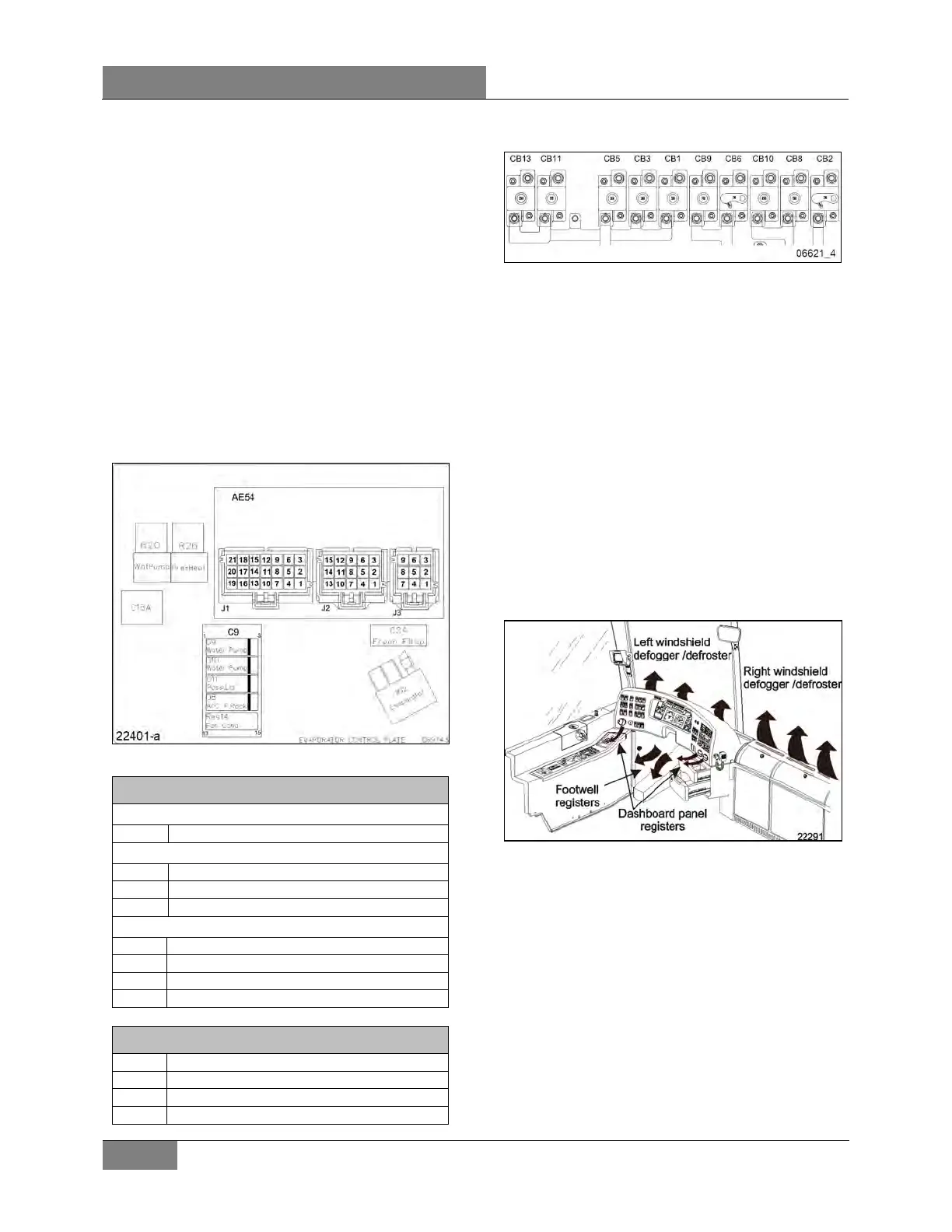
6. CENTRAL HVAC SYSTEM
The passenger’s unit evaporator fan, located in
the evaporator compartment on the L.H. side of
the vehicle is protected by circuit breaker CB3
90 amp with manual-reset mounted in the main
power compartment/junction panel (Figure 42).
The passenger’s unit condenser coil is mounted
on the opposite side of the evaporator. It is
ventilated by four brushless axial fans. The fan
motors are protected by circuit breakers located
in the VECR.
Furthermore, the following relays, diodes and
multiplex module are located in the evaporator
compartment. They are mounted on top of the
fan housing.
FIGURE 41: HVAC MODULE
A/C Junction Box
Water circulating pump relay
Overhead compartment Liq. Sol. Valve
Breakers in VECR
15A, Condenser fan up-fore
15A Condenser fan down-fore
15A Condenser fan down-aft
FIGURE 42: X3 SERIES REAR ELECTRICAL JUNCTION
PANEL WITH CIRCUIT BREAKERS
6.1 AIR CIRCULATION IN DRIVER’S AREA
Fresh air is taken from a plenum underneath the
front service compartment and enters the mixing
box through a ON/OFF damper. Return air is
taken through the right console into the mixing
box (Figure 51). Mixed air goes through cooling
and heating coils, fans and discharge ducts.
Both right and left discharge ducts defrost one
half of the windshield. The driver can also divert
some air flow to the console, from which he can
direct air to his knees and/or upper body with
adjustable HVAC air registers and to his feet
with the appropriate button (see FIGURE 43 and
Owner’s or Operator’s manual).
FIGURE 43: DRIVER’S UNIT AIR CIRCULATION
An additional air is located in the stepwell for
step de-icing (Figure 2). This airflow is supplied
by the passengers’ air ducting system.
6.2 AIR CIRCULATION IN PASSENGER’S
AREA
Fresh air enters from the left side of the vehicle
through a damper located on the evaporator
compartment door (Figure 44).
The damper can be fully opened for normal
operation or partially closed for extreme weather
or highly polluted areas. The recirculation REC
button is located on the HVAC control unit.
 Loading...


