DOB 1300-1556 | X3-45 Commuter PA-1648 Maintenance Manual Section 11 revised Jan 2021
2.3 REMOVAL AND REINSTALLATION
The following procedure deals with the removal
of the drive axle assembly and its attachments
as a unit. The method used to support the axle
during removal and disassembly depends upon
local conditions and available equipment.
1. Raise vehicle from the front wheels and
drive axle wheels. Place jack stands under
the rear chassis hoisting points. Remove
drive axle wheels (if required, refer to
Section 13, "Wheels, Hubs and Tires".
2. Exhaust compressed air from the air supply
system by opening the drain cock on each
air reservoir.
3. Disconnect the propeller shaft as directed in
Section 9, "Propeller Shaft", in this manual.
5. Disconnect the lower end both height
control valve link then move the arm up to
exhaust air suspension.
6. Disconnect the ABS speed sensors
connector located over the differential
housing.
When removing drive axle, if unfastening
cable ties is necessary for ease of operation,
remember to replace them afterwards.
7. Disconnect the air brake supply hoses over
the differential carrier.
Position the hoses so they will not be
damaged when removing the axle.
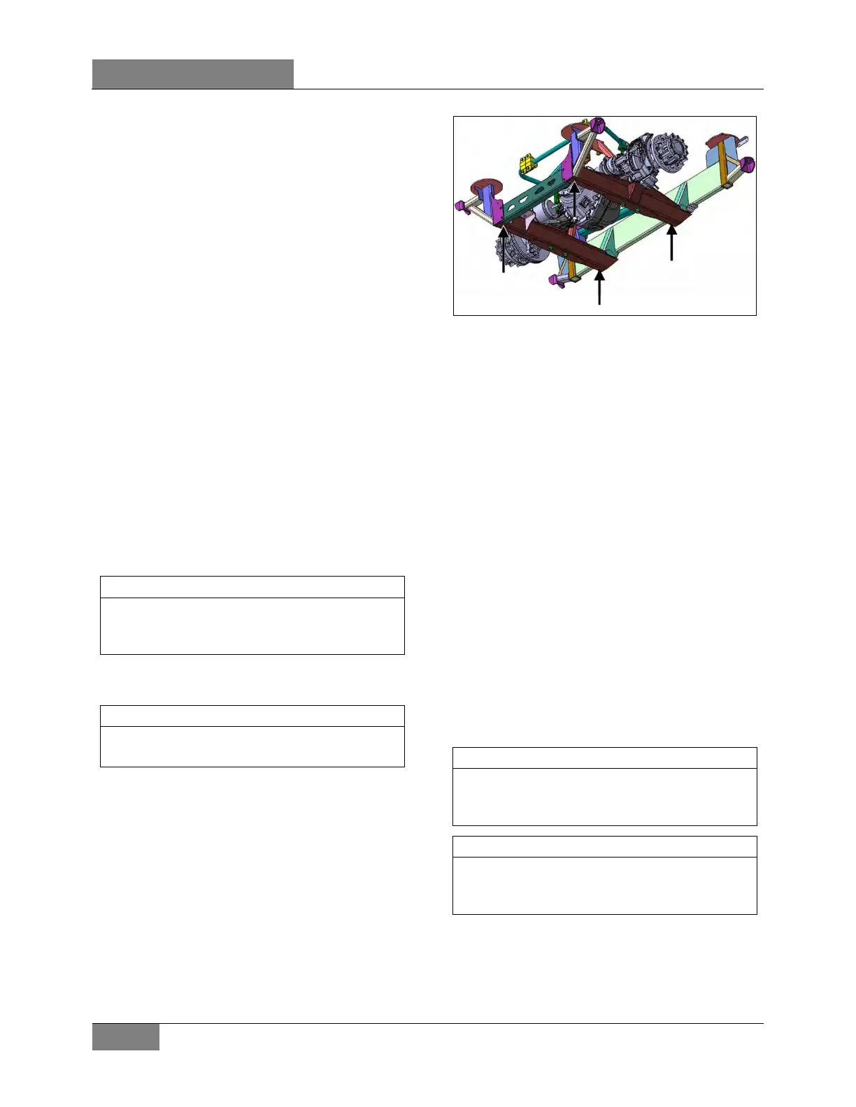
8. Install jack stands under the drive axle
subframe at the four locations shown on
FIGURE 4.
FIGURE 4: SUPPORT THE DRIVE AXLE SUBFRAME AT
THE FOUR LOCATIONS SHOWN
9. Disconnect the lower ends of the four shock
absorbers as outlined in Section 16,
"Suspension" under heading "Shock
Absorber Removal".
10. Remove the two sway bar links.
11. Remove the lower and upper longitudinal
radius rod supports as outlined in Section
16, "Suspension", under heading "Radius
Rod Removal".
12. Remove the transversal radius rod (panhard
bar).
13. Remove the two retaining nuts from each of
the four air springs lower mounting
supports.
14. Disconnect the drive axle speed sensor.
15. Use the jacks to lower axle. Carefully pull
away the drive axle assembly from
underneath vehicle.
16. Reverse removal procedure to reinstall drive
axle.
Refer to Section 16, “Suspensio
n” for
suspension components' proper tightening
torques.
Refer to section 13 "Wheels, Hubs And Tires"
for correct wheel bearing adjustment
procedure.
 Loading...


