DOB 1300-1556 | X3-45 Commuter PA-1648 Maintenance Manual Section 11 revised Jan 2021
2.4 DISASSEMBLY, REASSEMBLY,
ADJUSTMENT AND TORQUE CHART
Disassembly and re-assembly procedures are
covered in the following manual:
• ZF AXLE A132 REPAIR MANUAL #5871 207 002E
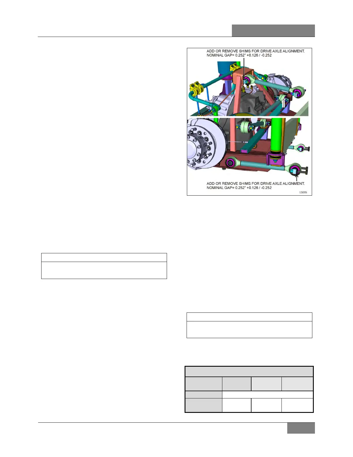
2.5 ZF A132 DRIVE AXLE ALIGNMENT
The drive axle alignment consists in aligning the
axle according to the frame. The axle must be
perpendicular to the frame. The alignment is
achieved with the use of shims inserted between
the lower longitudinal radius rod supports and
the frame.
Drive axle alignment is factory set and is not
subject to any change, except if the vehicle has
been damaged by an accident or if there are
requirements for replacement.
If the axle has been removed for repairs or
servicing and if all the parts are reinstalled
exactly in the same place, the axle alignment is
not necessary. However, if the suspension
supports have been replaced or altered, proceed
with the following instructions to verify or adjust
the drive axle alignment.
When drive axle alignment is modified, tag
axle alignment must be re-verified.
2.5.1 Procedure
1. Park vehicle on a level surface, then chock
front vehicle wheels.
2. Using two jacking points (which are at least
30 inches [76 cm] apart) on drive axle, raise
the vehicle sufficiently so that wheels can
turn freely at about ½ inch from ground.
Secure in this position with safety stands,
and release parking brake.
3. Install wheel mount sensors on front end
and drive axle wheels (Figure 8).
Select axle specifications in the appropriate
chart.
4. With the system installed as in Figure 8,
adjust drive axle according to specifications'
chart below.
0°
 Loading...


