SECTION 22: HEATING AND AIR CONDITIONING
DOB 1300-1556 | X3-45 Commuter PA-1648 Maintenance Manual First release Oct 2020
filter dryer again and replace the moisture-
liquid indicator.
9. After approximately 7 days of operation,
recheck the compressor oil for cleanliness
and acidity.
6.7.4 Pumping Down
This procedure is intended to reduce refrigerant
loss, on the central system only, by isolating it in
the compressor and the receiver tank, as well as
in their connecting line, in order to carry out
repairs on other sections of the air-conditioning
system (lines and components).
Once this pull down procedure has been
properly done, any component from the outlet
hose on the receiver tank, the filter dryer, the
liquid solen
oid valves, the evaporators, the
expansion valves, and all lines associated with
them can be serviced,
evacuated.
It must be noted that there is STILL refrigerant
under pressure in the compressor, the
discharge lines, condenser, and receiver tank
and that these items cannot be serviced. To
service these items, it is required to recover
the refrigerant using a recovery unit.
CAUTION
The filter dryer should be changed each time a
line in the system is opened.
Before attempting a
compressor and receiver tank, use a recovery
unit to remove refrigerant from the system.
WARNING
To prevent any injury, when the air
conditioning system must be opened, refer to
previous paragraph “Precautions In Handling
Refrigerant” to prevent any injury.
For this procedure to be done properly, it is
assumed the proper amount of refrigerant is in
the refrigeration system. If there is any doubt,
use a recovery unit to recover and weight the
amount of refrigerant in the system.
On vehicles equipped with small HVAC
systems, refer to “
Service Manual ".
Procedure
1. Energize driver’s unit and passengers’ unit
(main HVAC system) section liquid solenoid
valve. To do so, connect male and female
connector housings of C24 together for the
passengers’ area (found on the HVAC
module in the evaporator compartment) and
C44 for the driver's area (located on the
ceiling of the spare wheel compartment).
During normal use, both male and female
housings of connector C24 and C44 are
kept unplugged.
CAUTION
Connectors C24 & C44 must be disconnected
and their caps reinstalled after this procedure.
Leaving them connected will keep the driver’s,
passengers and overhead compartment liquid
solenoid valves open, and resul
t in battery
draining if the vehicle remains unused for
several days.
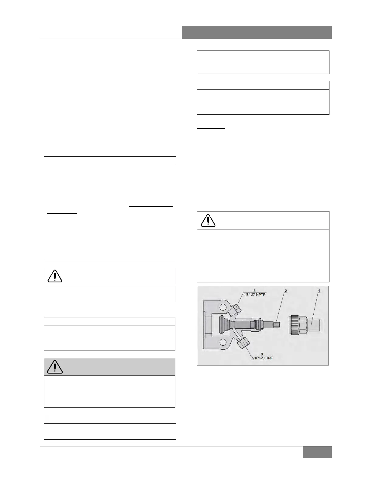
FIGURE 56: COMPRESSOR SHUTOFF VALVE
BACKSEATED POSITION (NORMAL OPERATING
POSITION)
 Loading...


