SECTION 22: HEATING AND AIR CONDITIONING
DOB 1300-1556 | X3-45 Commuter PA-1648 Maintenance Manual First release Oct 2020
• Check the oil level first, according to
“Maintenance - Oil Color & Level Check”.
• Connect the refrigerant recovery station to
the service connections of the shut-off
valves.
• Isolate the compressor from the system. To
do so, front seat the compressor shutoff
valves.
• Extract the refrigerant using the recovery
station until ambient pressure is reached.
Take note of the quantity removed.
• Remove the magnetic drain plug.
FIGURE 20: OIL FILL PLUG (A) AND SIGHT GLASS (B)
• Drain the oil into a container. Measure the
quantity of oil removed.
• Extract and clean the oil filter/strainer.
Reinstall once done.
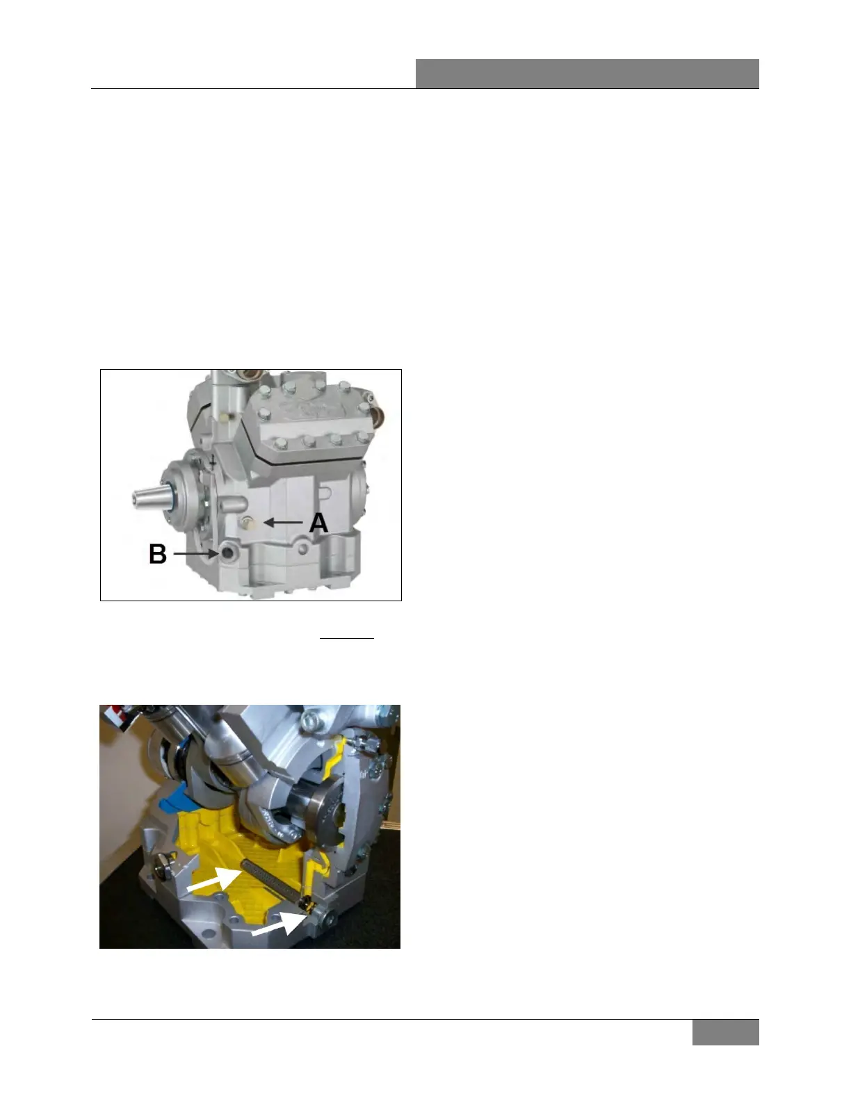
FIGURE 21: CUTAWAY VIEW SHOWING OIL
FILTER/STRAINER AND MAGNETIC DRAIN PLUG
• Clean the magnetic drain plug and reinstall.
• Through the oil filling port, add the same
amount of fresh oil. More oil should be added
if the oil level was too low when checked at
the beginning.
• Evacuate the compressor to 500 microns.
• Charge the system with new refrigerant.
Charge with the same quantity as recovered
previously.
4.1.6 Troubleshooting Guide
A preliminary check may be made by simply
feeling the cylinder heads with the unit in
operation at ambient temperatures of 35
o
F (2
o
C)
and over. The cylinder heads are internally
divided into suction and discharge areas. The
upper central section of the cylinder is the
suction side and it should be relatively cool to
the touch, as opposed to the hot discharge area
which is the lowest perimeter area of the
cylinder head. If a valve plate or head gasket is
blown, or a compressor unloader is stuck open,
partially compressed refrigerant vapor will be
circulated between the suction and discharge
sides of the head. The affected cylinder head
will then have a relatively even temperature
across its surface and be neither as hot as the
normal discharge temperature nor as cool as the
normal suction temperature.
Blown Head Gaskets
Symptom:
• Loss of unit capacity at low temperature.
• Even cylinder head temperature.
Cause:
• Improperly torqued cylinder head bolts.
• Improperly positioned gasket at assembly.
• Warped cylinder head.
• Severe liquid refrigerant flood back.
Blown Valve Plate Gaskets
Symptom:
• Loss of unit capacity at medium and low
temperatures.
• Very hot cylinder head surface.
• Higher than normal suction pressure.
Cause:
• Improperly torqued cylinder head bolts.
 Loading...


