DOB 1300-1556 | X3-45 Commuter PA-1648 Maintenance Manual First release Oct 2020
6.2 HEIGHT CONTROL VALVES
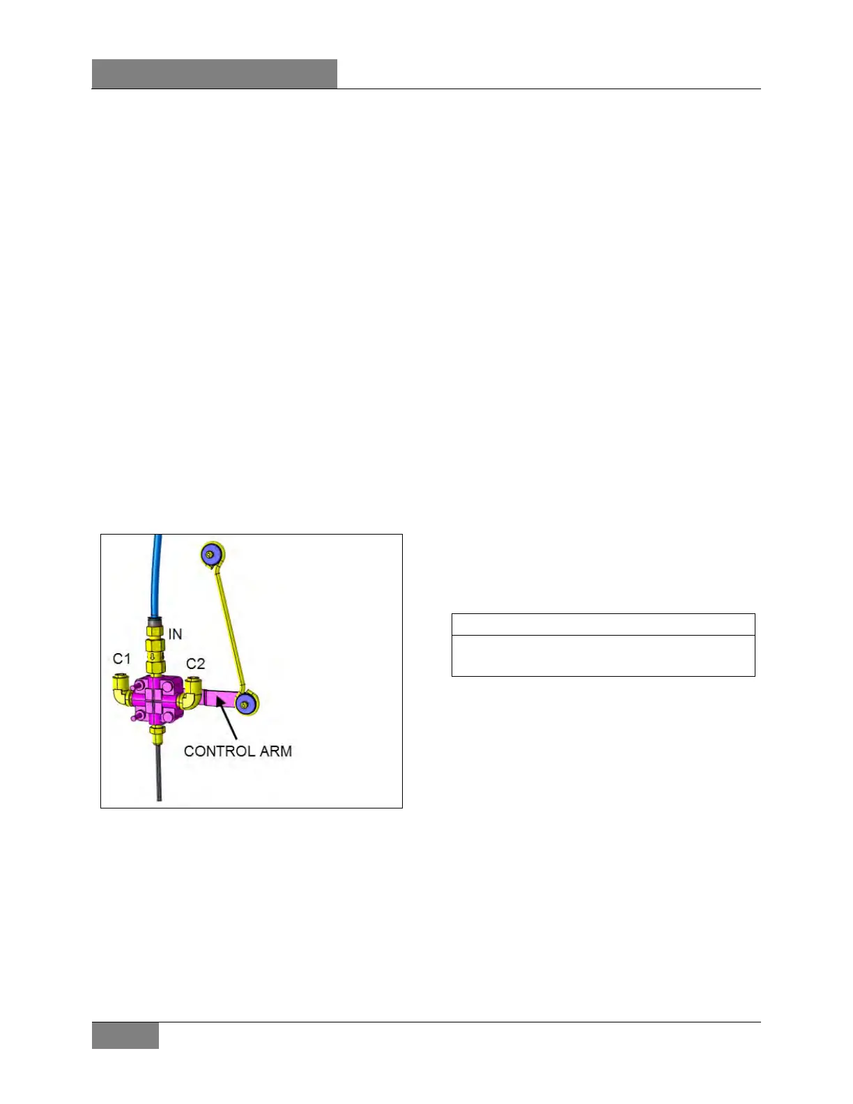
The height control valves automatically add air
to, or release air from air springs to maintain
constant suspension height regardless of load,
or load distribution. Each valve adjusts
independently according to the following
conditions:
Loading position
As the load increases and lowers the vehicle
body, the control arm commands the height
control valve to add air to air springs.
Neutral position
When vehicle body reaches the normal ride
height, the height control valve control arm
reaches the "neutral" position and keeps both
the supply and exhaust ports closed to ensure
normal ride height is maintained. This condition
remains static until the vehicle load is altered.
Unloading position
As the load decreases and raises the vehicle
body, the control arm commands the height
control valve to release air from air springs.
FIGURE 15: HEIGHT CONTROL VALVE 16093
6.3 MAINTENANCE
The height control valve requires no periodic
maintenance. Height control valve linkage
operates on rubber bushings and no lubrication
should be attempted at this point. Inspect the
valve for loose joints, air leaks and worn
bushings.
6.3.1 Removal and installation
Before disconnecting any height control valve air
lines, securely support the vehicle by its jacking
points on the body, and place safety support
underneath body. Refer to "VEHICLE JACKING
POINTS" in Section 18, "Body".
1. Exhaust air from air system by opening the
drain cock on accessory air reservoir.
Remove height control valves.
2. Disconnect overtravel lever from link and
pull down lever to exhaust remaining air from
air springs.
3. Disconnect air supply and delivery lines from
the height control valve. Cover ends of the
lines with tape to prevent entry of foreign
matter.
4. Remove the nuts retaining the height control
valve to the mounting bracket, then remove
valve assembly.
Note: The height control valve bolts
equipped with a nylon insert should be
replaced after the third (3rd) tightening.
Reverse removal procedure to replace height
control valve. After installation, check for leakage
using a soap and water solution.
6.3.2 Air leakage test
The following procedure applies when valve
assembly has been removed from vehicle.
1. Clean the exterior of valve assembly.
2. Connect air pressure line to air inlet port,
then allow air pressure build-up (70- 100 psi
(480 - 690 kPa)).
3. Dip the valve assembly in a container full of
water, and watch for air bubbles when the
control arm is in the center position. No air
should escape from any point of the valve
assembly.
4. If bubbles appear from the air spring port,
this is an indication that the air inlet valve
assembly is defective and must be replaced.
5. Remove air pressure line from air inlet fitting
and connect it to the air spring port. If
bubbles appear at the air inlet check valve
port, this is an indication that the check valve
unit is defective and must be replaced.
 Loading...


